Apparatus in a Drill String

Inactive Publication Date: 2005-04-21
INTELLISERV
View PDF99 Cites 128 Cited by
  • Summary
  • Abstract
  • Description
  • Claims
  • Application Information

AI Technical Summary

Benefits of technology

[0016] The inside surface may comprise a transition region comprising a plurality of diameters and forming a convex region and a concave region in the inside surface of the drill pipe. It is believed, but not wanting to be bound by any theory, that the spiral weld of the line

Problems solved by technology

The upsetting process, therefore, results in an overall ch

Method used


Image

  • Apparatus in a Drill String
  • Apparatus in a Drill String
  • Apparatus in a Drill String

Examples


Embodiment Construction

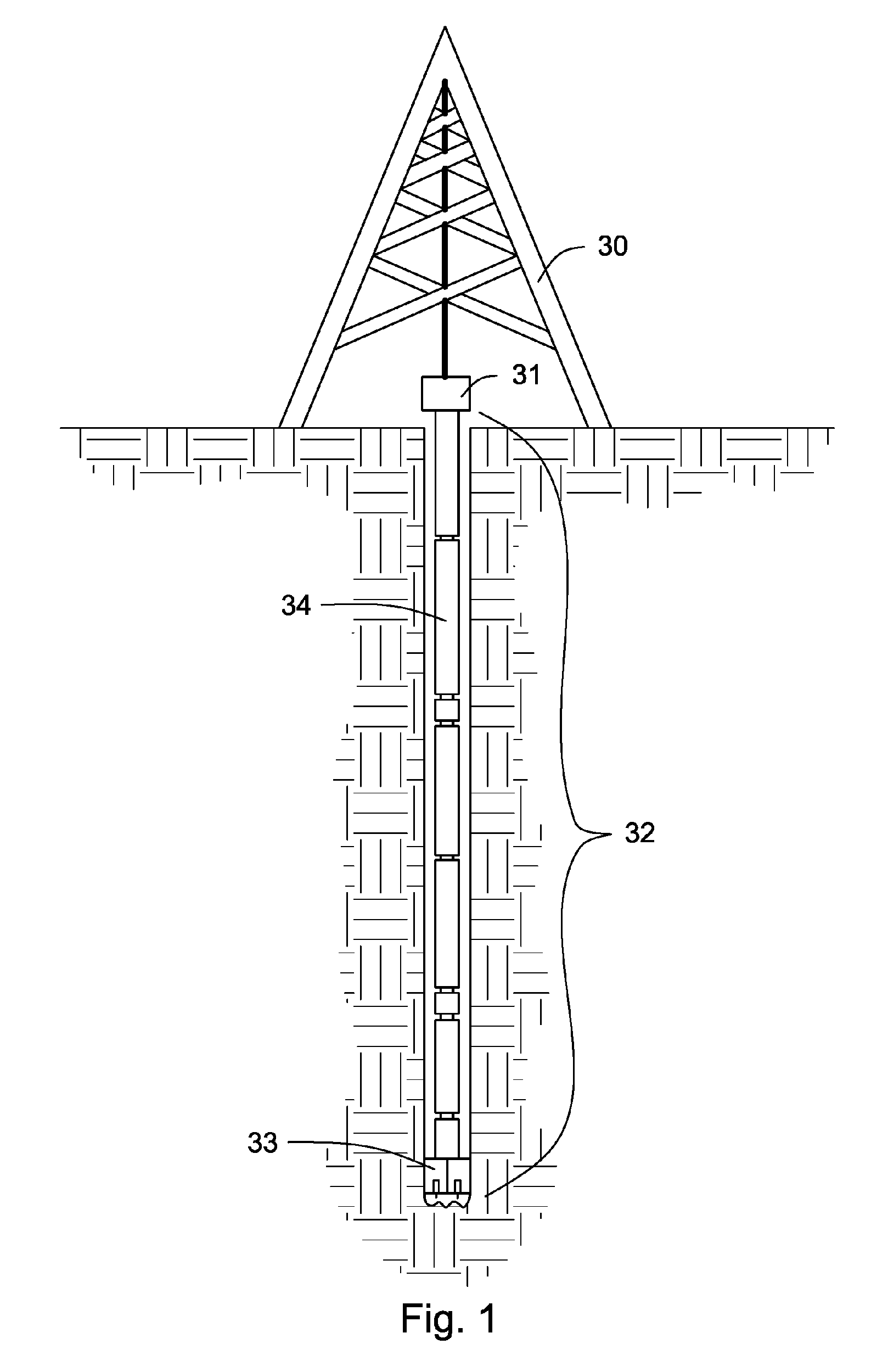
[0028]FIG. 1 shows an embodiment of a drill string 32 suspended by a derrick 30. The drill string 32 comprises a multiplicity of drill pipe 34 intermediate a bottom hole assembly 33 and a swivel 31. The bottom hole assembly 33 may comprise drill bits, hammers, sensors, and other tools that may aid in drilling. The swivel 31 may provide stability to the drill string 31. In one aspect of the invention the drill string 32 is capable of transmitting electrical signals from bottom hole assembly 33 or other points along the drill string 32 to the surface. Such a system is disclosed in U.S. Pat. No. 6,670,880 to Hall, et al, which is herein incorporated by reference.

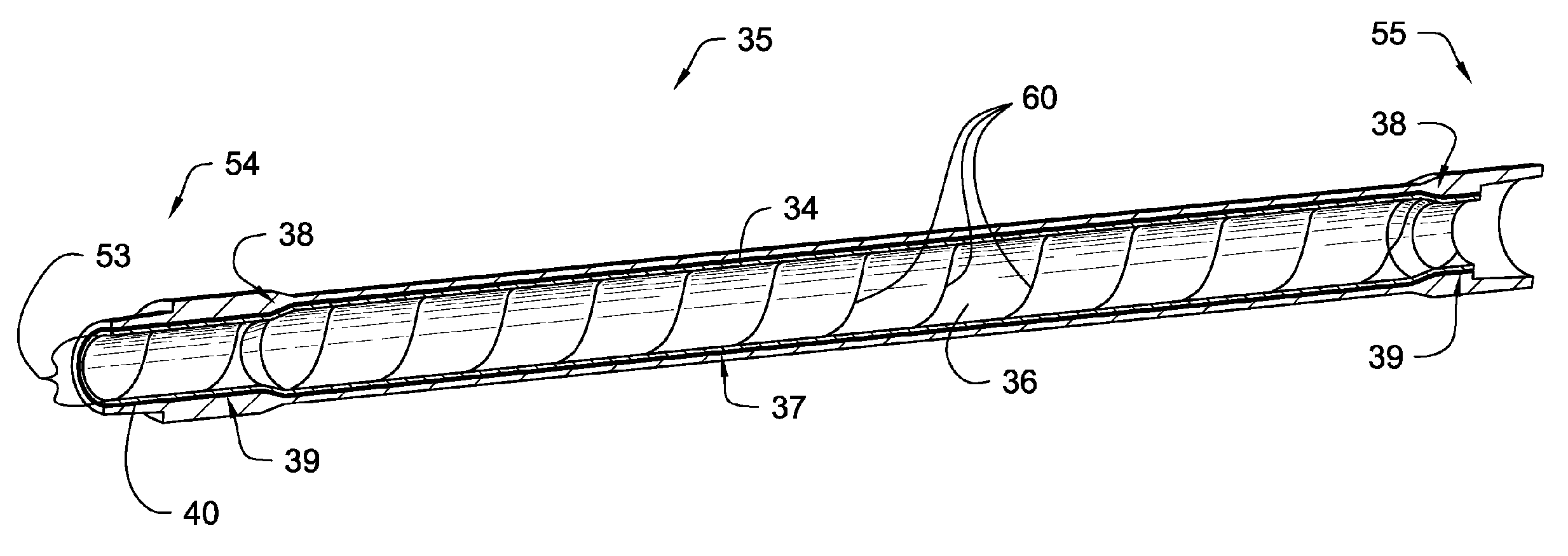
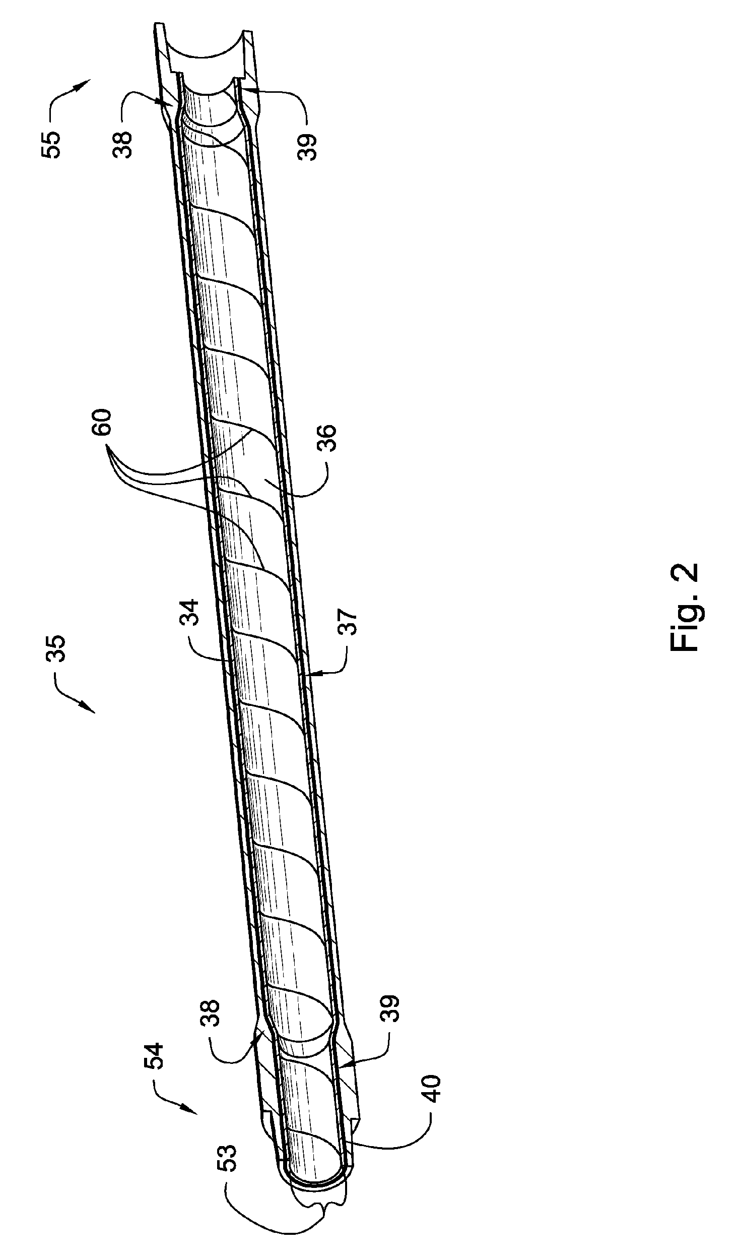
[0029]FIG. 2 is a cross sectional view of the apparatus 35 comprising an internally upset drill pipe 34 with a conformable spirally welded metal tube 36 disposed within a central bore 53 of the drill pipe 34. Transition regions 38 comprising a plurality of diameters that lie intermediate a first diameter 39 and a second diamet...


PUM


Abstract

An apparatus in a drill string comprises an internally upset drill pipe. The drill pipe comprises a first end, a second end, and an elongate tube intermediate the first and second ends. The elongate tube and the ends comprising a continuous an inside surface with a plurality of diameters. A conformable spirally welded metal tube is disposed within the drill pipe intermediate the ends thereof and terminating adjacent to the ends of the drill pipe. The conformable metal tube substantially conforms to the continuous inside surface of the metal tube. The metal tube may comprise a non-uniform section which is expanded to conform to the inside surface of the drill pipe. The non-uniform section may comprise protrusions selected from the group consisting of convolutions, corrugations, flutes, and dimples. The non-uniform section extends generally longitudinally along the length of the tube.

Description

CROSS REFERENCE TO RELATED APPLICATIONS [0001] The present application is a continuation-in-part of co-pending U.S. patent application Ser. No. 10 / 710,936 filed on Aug. 13, 2004, which is herein incorporated by reference. U.S. patent application Ser. No. 10 / 710,936 is a continuation-in-part of U.S. patent application Ser. No. 10 / 212,187 filed on Aug. 5, 2002, which is herein incorporated by reference.FEDERAL SPONSORSHIP [0002] This invention was made with government support under Contract No. DE-FC26-01NT41229 awarded by the U.S. Department of Energy. The government has certain rights in the invention.BACKGROUND OF THE INVENTION [0003] This invention relates to an apparatus in a drill string. Specifically, this invention is a spirally welded metal tube having its original diameter sufficiently reduced by the formation of non-uniform protrusions on its surface so that it may be inserted into the bore of an internally upset drill pipe. The spirally welded metal tube is disposed within...

Claims


Application Information

Patent Timeline
IPC IPC(8): E21B17/00E21B17/10E21B43/10
CPCE21B17/003E21B43/103E21B17/1007
Inventor HALL, DAVID R.DAHLGREN, SCOTTHALL, TRACY H. JR.FOX, JOEPIXTON, DAVID S.
Owner INTELLISERV
Why Eureka
Try Eureka