

Method and apparatus for homogenisation of melt
- Summary
- Abstract
- Description
- Claims
- Application Information
AI Technical Summary
Benefits of technology
Problems solved by technology
Method used
Image

Examples
example 1
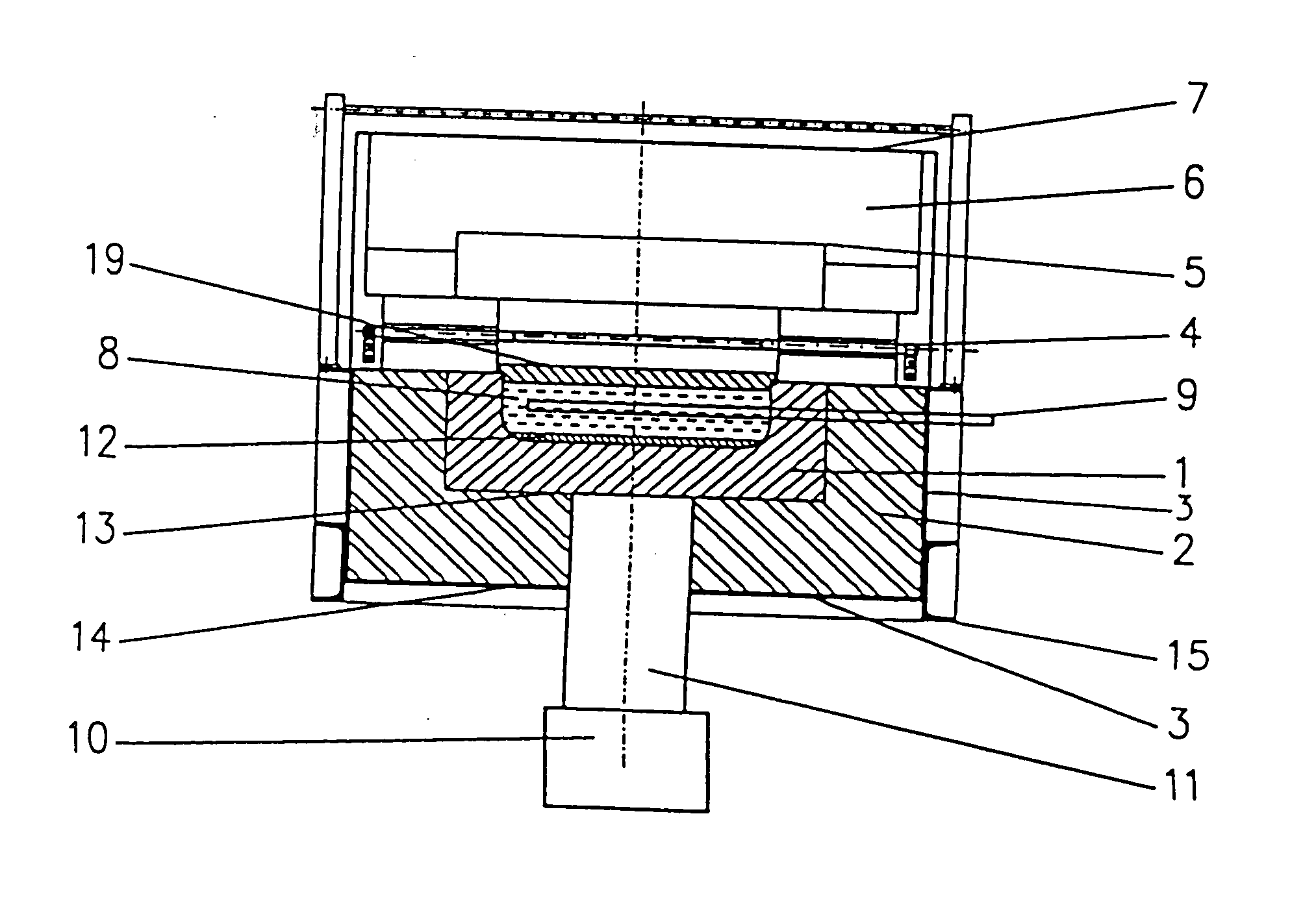
[0030] (FIG. 1)
[0031] Refractory channel 1 of the forehearth has a rectangular section in vertical section perpendicular to longitudinal axis of the channel 1. Dielectric melt, e.g. glass melt 8, flows thorough the channel 1. The channel 1 is surrounded by thermal insulation 2 in the steel casing 3. The channel 1 is heated above the glass melt 8 by electric resistance elements 4 or non-showed burners in the same locations. The channel 1 is covered above the surface of the molten glass 8 by a roof 5, covered by top insulation 6. The surface of glass is covered by submerged surface plate 19. The top construction of the channel 1 is covered by shielding metallic sheet 7, connected with the metallic casing 6 in the channel 1. Metallic rods 9 e.g. molybdenum, are immersed in the molten glass 8. The microwave field is introduced into the molten glass 8 from the source 10 of microwave radiation by waveguide 11 positioned at the bottom of the channel 1 and passing through the opening in th...
example 2
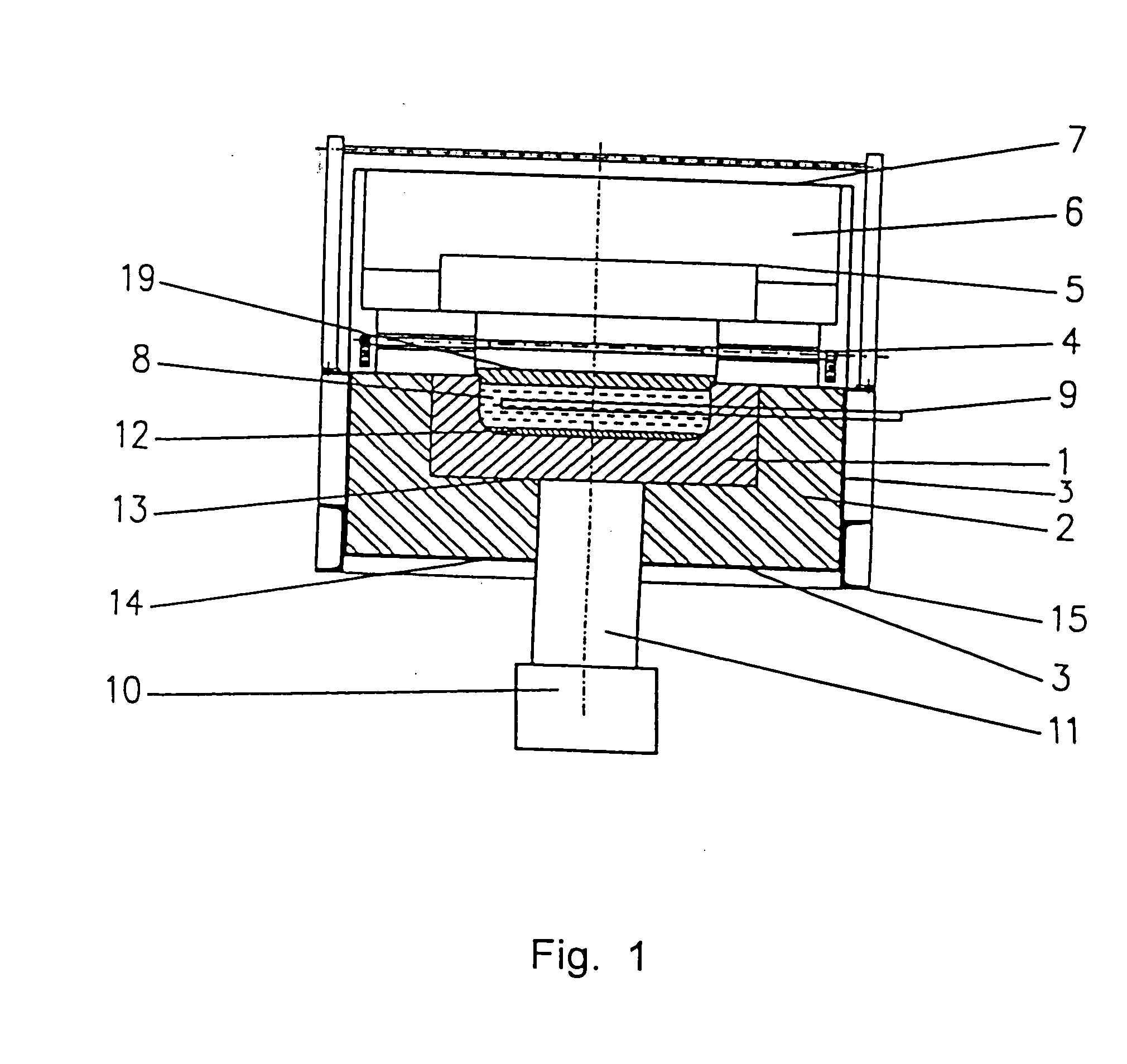
[0041] (FIG. 2)
[0042] In case the refractory channel 1 of the forehearth cannot be cooled, arrangement of the waveguides 11 per FIG. 2 is convenient, i.e. one waveguide 11 is positioned at the bottom 14 of the metallic casing 3 and one waveguide 11 is positioned above the surface of the molten glass 8. The bottom waveguide 11 passes through the bottom 14 of the metallic casing 3, possibly under its anchoring 15. The top waveguide 11 passes through the top shielding plate 7, top insulation 6 and roof 5. This design is suitable, if the refractory channel 1 of the forehearth is made of material with very low permitivity, e.g. Al2O3 or SiO2 content. Introducing the microwave energy from the top, as is also designated in FIG. 2, is convenient mainly when using gas burners 23 for heating.
example 3
[0043] (FIG. 3)
[0044] Molten glass 8 is entering through an throat 21 from the melting area of the furnace 5 into the furnace working end and exiting through an outlet 22 for further processing, e.g. into the refractory channel 1 of the forehearth.
[0045] The waveguides 11 are positioned to the outer surface of the refractory walls of the basin 16 of the working end containing molten glass 8. The basin 16, compared with the previous channel 1 of the forehearth, has larger depth and width. The basin 16, has rectangular section in a cross section perpendicular to its longitudinal axis. Large quantity of corrosive melt 12 is accumulated at the bottom 17 of the basin 16 of working end, which has to be homogenized with the base molten glass 8 in the basin 16. The waveguides 11 are positioned at the bottom 17 of the basin 16 of the working end and also at the side walls 18 of the basin 16. An advantage of microwave field effect on the corrosive melt 12 in the basin 16 and having insulati...
PUM
| Property | Measurement | Unit |
|---|---|---|
| Viscosity | aaaaa | aaaaa |
| Frequency | aaaaa | aaaaa |
| Dynamic viscosity | aaaaa | aaaaa |
Abstract
Description
Claims
Application Information