Gas release valve for paintball marker

a technology of gas release valve and paintball marker, which is applied in the direction of valve operating means/releasing devices, functional valve types, mechanical apparatus, etc., can solve the problems of ball breakage or “chopping”, inherently limited capacity, and high velocity, and achieves convenient disassembly and cleaning. , the effect of improving the ease of assembly

Inactive Publication Date: 2005-04-21
NEW DESIGNZ
View PDF15 Cites 16 Cited by
  • Summary
  • Abstract
  • Description
  • Claims
  • Application Information

AI Technical Summary

Benefits of technology

[0023] A still further object of the present invention is to provide a new and improved gas release valve for a paintball marker having enhanced ease of assembly and which is easily disassembled for cleaning and service.

Problems solved by technology

For a given dwell, higher input pressures generally produce a greater volume of gas and generally result in higher velocities.
In addition to prolonging the cycle time, excessively long dwell is undesirable because it can cause “blow back” which can force the next paintball back up the feed tube and contribute to ball breakage or “chopping”.
However, their capacity is inherently limited and a player can quite literally run out of gas.
The cylindrical coil spring in the compressed gas chamber reduces the volume of the chamber and causes additional turbulence.
Also, the intersection of perpendicular bores includes unnecessary dead volume that must be filled by the expanding propellant charge before sufficient force is transferred to the projectile to cause it to move out of the barrel.
Still further, the intersection of perpendicular bores typically include turbulence-causing corners.
The multiple exhaust passages, annular recess and space around the valve body dramatically increase the dead volume in the valve.
The internal turbulence, multiple changes of direction and increased dead volume of the '920 flow passage design result in less than optimal fluid flow through the valve.
A further deficiency of the valve configuration disclosed in the '920 patent is that the valve stem is largely unsupported as it passes through the center of the valve body.
This unsupported configuration presents the possibility of valve seal misalignment with the intake port.
Misalignment of the seal with its seat may result uneven seal wear and / or in leakage through the valve.

Method used


Image

  • Gas release valve for paintball marker
  • Gas release valve for paintball marker
  • Gas release valve for paintball marker

Examples


Embodiment Construction

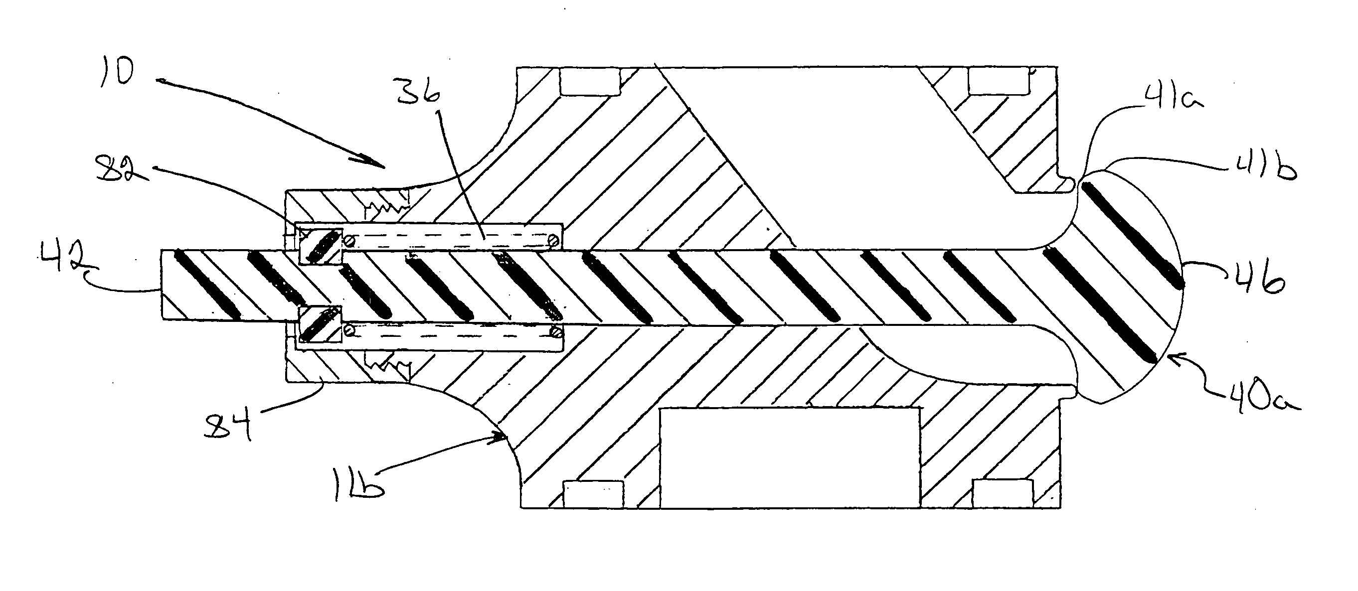
[0033] Illustrated embodiments of a gas release valve in accordance with the present invention will be described with reference to FIGS. 4-9.

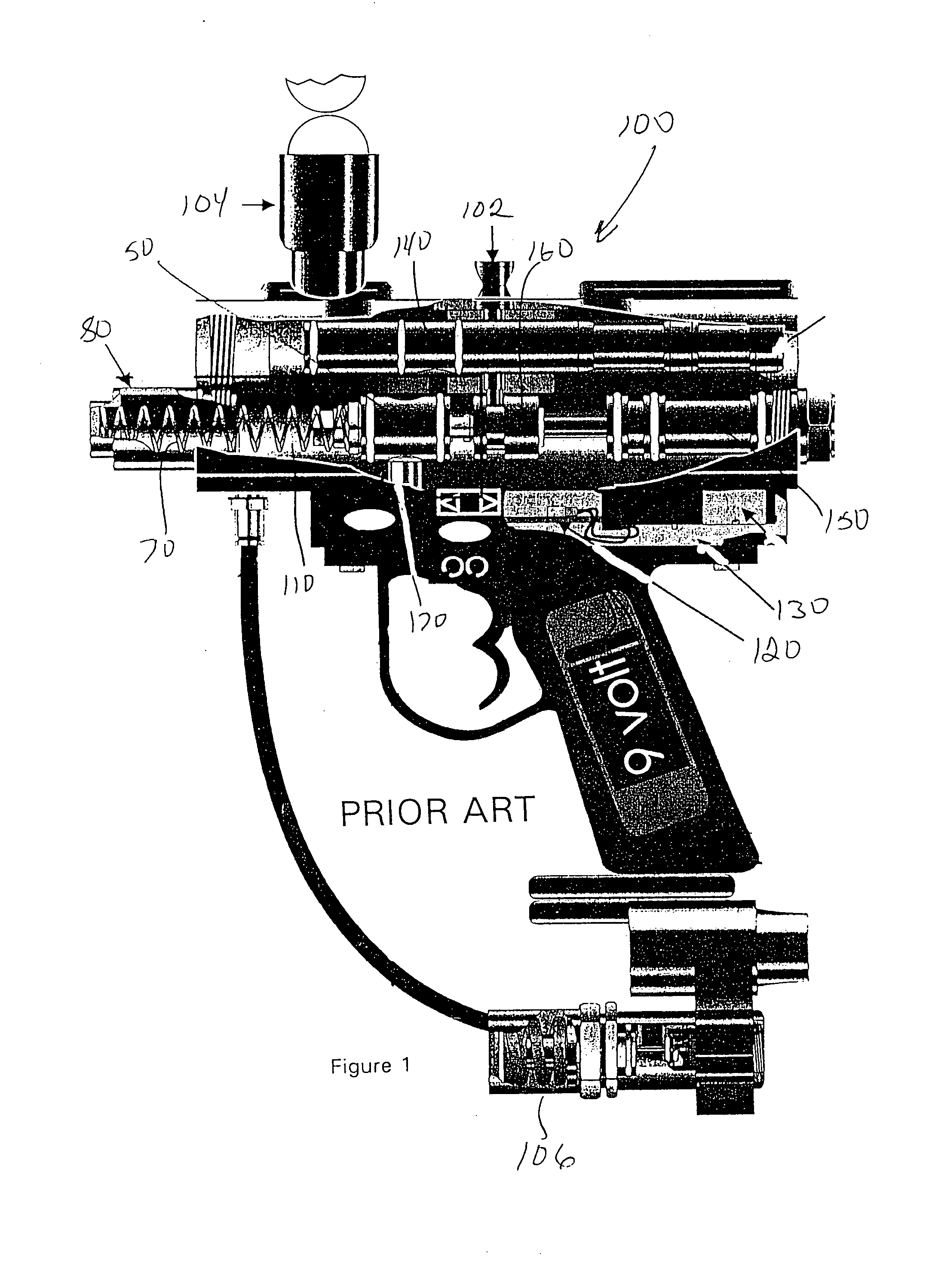
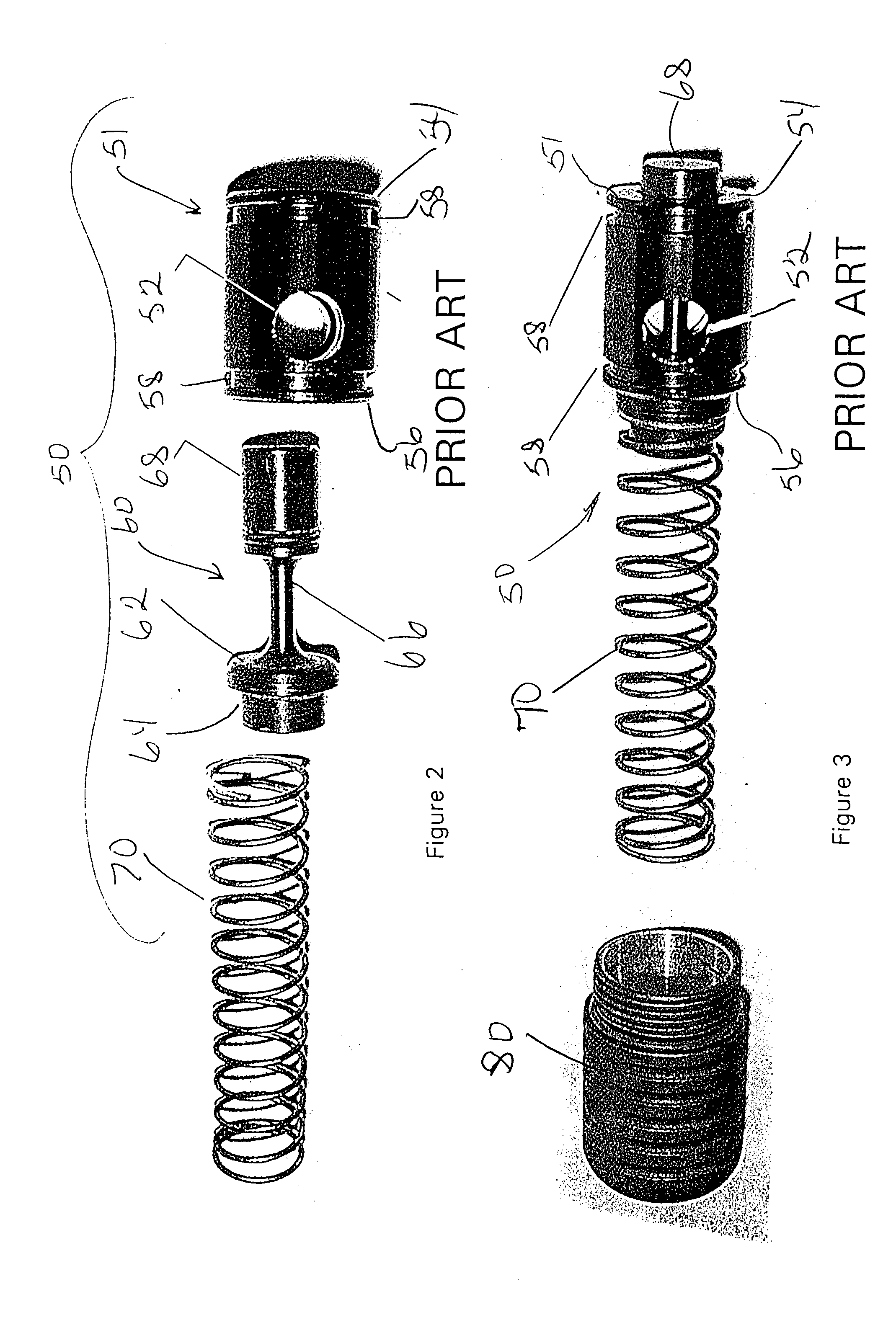
[0034]FIG. 1 illustrates a prior art paintball marker 100 that may be equipped with the gas release valve embodiments shown in FIGS. 4-6. FIGS. 2 and 3 show exploded and pre-assembly top views of a prior art gas release valve 50 of the type that may be replaced by the illustrated gas release valve shown in FIGS. 4-6. A regulator 106 provides compressed gas to several chambers of the paintball marker 100 of FIG. 1 at a predetermined pressure. The compressed gas fills a compressed gas chamber 110 containing the valve bias spring 70 toward the left side of FIG. 1. Compressed gas also fills an internal chamber (not illustrated) in communication with a solenoid valve 130. An electronic circuit 120 controls actuation of the solenoid valve 130. A reciprocating bolt 140 is coupled to a reciprocating hammer 160 by a bolt pin 102 passing through the bol...


PUM


Abstract

A gas release valve for a paintball marker employs a uniquely configured gas flow passage to improve gas flow through the valve and enhance the performance and efficiency of the marker. A short axial intake portion of the gas flow passage meets an angled exhaust portion at an angle of approximately 120°. A transition surface at the intersection of the intake and exhaust portions is at least partially defined by a portion of a sphere. The valve body defines an internal spring chamber in which an elastic o-ring engages a radial groove on the valve stem to hold the valve bias spring in compressed relationship inside the spring chamber. The o-ring also seals the valve stem to the valve body and supports the valve during reciprocation. The disclosed valve configuration improves the efficiency and ease of assembly and disassembly of the gas release valve.

Description

BACKGROUND OF THE INVENTION [0001] 1. Field of the Invention [0002] This invention relates to pneumatically operated projectile launching devices and more particularly to a gas release valve for such a projectile launching device configured to significantly improve the efficiency of gas flow through the valve. [0003] 2. Description of the Related Art [0004] Paintball is a popular recreational activity that may be played in a variety of indoor or outdoor environments. Typically, the object of the game is to capture the flag of an opposing team. Players are eliminated when “marked” by paint from a pneumatically fired paint ball. The ball is designed to rupture and splatter paint on the stricken player. The equipment used to fire the paintballs are referred to as “markers”. Paintball markers launch the paintballs by releasing a burst of gas (typically CO2, compressed air or Nitrogen) under pressure into a barrel behind the paintball projectile. [0005] The development of paintball marke...

Claims


Application Information

Patent Timeline
Patent Type & Authority Applications(United States)
IPC IPC(8): F16K1/12F41B11/73
CPCF16K1/12F41B11/73F41B11/57F41B11/71
Inventor DZIOB, DAVID F.BLAZEK, ANTONIN
Owner NEW DESIGNZ
Why Eureka
Try Eureka