Method and apparatus for increasing the linearity and bandwidth of an amplifier

a linearity and amplifier technology, applied in the field of signal processing, can solve problems such as phase mismatch, increase in data processing rate, and current mirror performance undetected reduction

Active Publication Date: 2005-04-21
MARVELL ASIA PTE LTD
View PDF3 Cites 89 Cited by
  • Summary
  • Abstract
  • Description
  • Claims
  • Application Information

AI Technical Summary

Benefits of technology

[0008] In one embodiment at least one semiconductor device in the first current mirror path comprises a field effect transistor and the at least one semiconductor device in the second current mirror path comprises a field effect transistor. It is contemplated that the positive feedback device comprises cross-coupled capacitor. In one embodim

Problems solved by technology

Increases in data processing rates and transmit rates challenge the circuits responsible for processing and transmitting the data.
When operation frequencies of current mirrors 102 increase (i.e. the signals passing through the current mirror), the current mirror performance may undesirably decrease due to inherent performance characteristics of the devices that make up the current mirror.
This delay results in a phase mismatch between the signal arriving along path S1 and the signal arriving along path S2.
This drawback becomes more pronounced as frequency increases and hence may become a roadblock to high speed operation.
Consequently, Iin does not match Iout and a basic property of current mirror operation is lost.
Moreover, the input signal will force the output impedance to vary while output linearity is also disrupted.
This is a significant drawback to current mirror operation.
While various solutions have been proposed, no prior art solution overcomes this drawback.
Fast in-band transitions in the input signal result in an un-cancelled drop in the drain-source voltage of the current mirror device which can drive the transistor into the linear region of operation, thus degrading the accuracy and linearity of the current mirror.
This is highly undesirable.

Method used


Image

  • Method and apparatus for increasing the linearity and bandwidth of an amplifier
  • Method and apparatus for increasing the linearity and bandwidth of an amplifier
  • Method and apparatus for increasing the linearity and bandwidth of an amplifier

Examples


Embodiment Construction

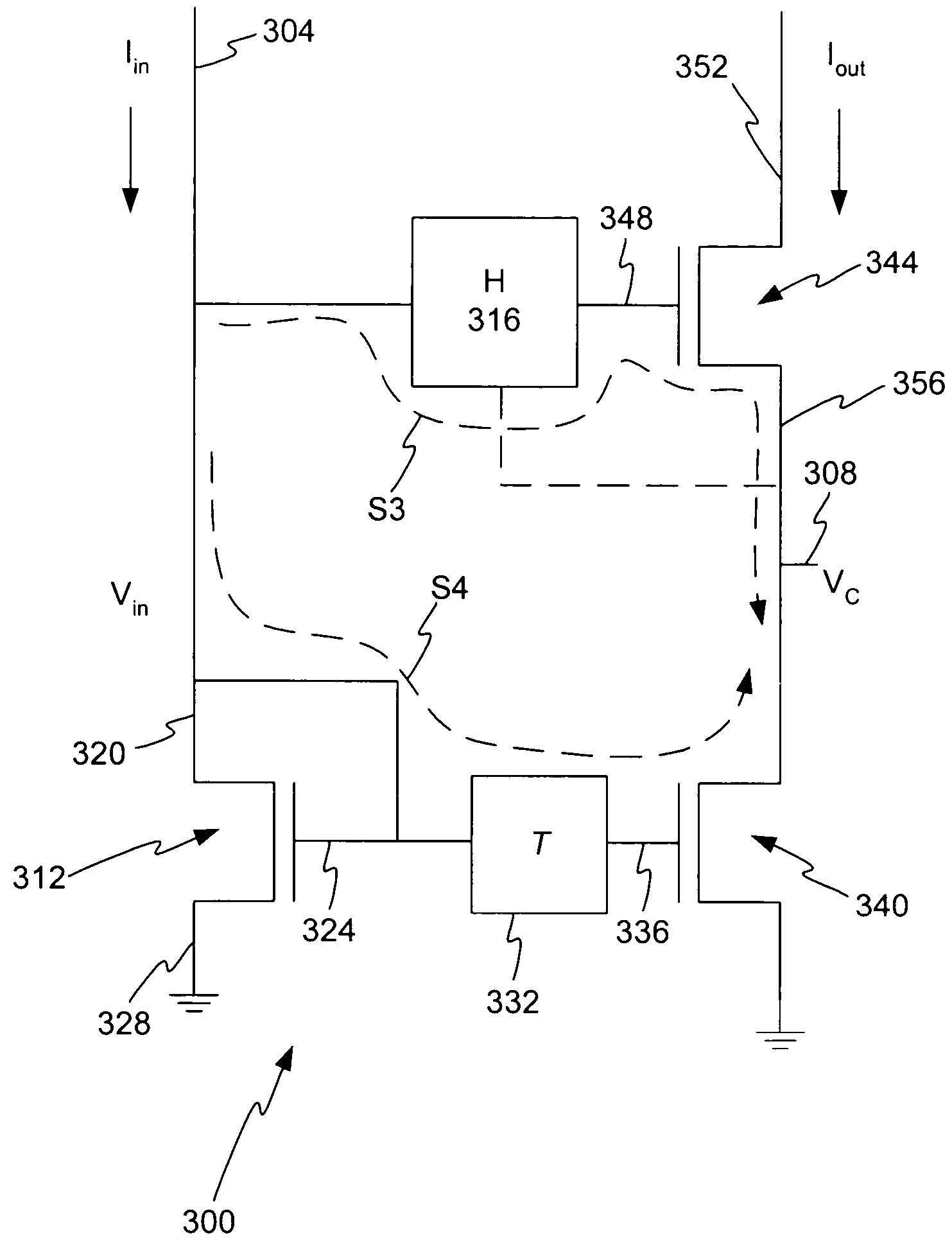
[0027]FIG. 3 illustrates an example embodiment of a current mirror 300 with a delay element 332. As shown a current mirror 300 having an input 304 provides an input signal to be mirrored or replicated at a current mirror output 352. The current mirror 300 may be configured to amplify the input signal by a factor N. The input 304 connects to a first semiconductor device 312 and second device 316. The second device 316 may comprise any type device configured to introduce a delay a signal or otherwise modify the signal phase or magnitude. In one embodiment the device 316 is configured with a low impedance for current input. In one embodiment the device 316 is configured to make Vc equal to or generally equal to Vin. In one embodiment the device 316 is configured to create a virtual ground at Vc. The second device 316 may comprise, but is not limited to, a source follower, operational amplifier, amplifier, and transconductor amplifier.

[0028] In the example embodiment shown in FIG. 3, t...


PUM


Abstract

A method and apparatus is disclosed for improving high frequency performance of an amplifier, such as for example, a current mirror. In one embodiment, a delay element is introduced in a current mirror signal path to account for signal propagation delay that may exist in one or more alternative signal paths. The delay element maintains desired phase alignment at a cascade node of the current mirror thereby establishing, in one embodiment, the cascode node (Vc) in an AC ground state. To extend current mirror high frequency capability an embodiment is disclosed having cross-coupled capacitors, active elements, or one or more other devices configured to provide positive feedback to one or more current mirror inputs. The positive feedback may be selectively configured to increase the operational bandwidth of the current mirror.

Description

1. FIELD OF THE INVENTION [0001] The invention relates to a method and apparatus for signal processing and in particular to a method and apparatus for improving the performance of a current mirror. 2. RELATED ART [0002] Increases in data processing rates and transmit rates challenge the circuits responsible for processing and transmitting the data. This is particularly true in the field of data communication where the demand for higher processing and transmit rates continues to grow. FIG. 1 illustrates an example embodiment of a particular configuration of a current mirror circuit. As is understood, the current mirror 102 is a commonly utilized building block of a communication circuit. As shown, a current mirror input 104 is duplicated or mirrored at an output 108. As current mirrors 102 are widely utilized and generally know in the art, a detailed discussion of current mirror operation is not provided. Of importance however, the current mirror may be considered as having two paths...

Claims


Application Information

Patent Timeline
IPC IPC(8): H03F1/32H03F1/48
CPCH03F1/3205H03F1/483H03F2203/45512H03F2200/36H03F3/45475H03F3/45273
Inventor GRILO, JORGE ALBERTO
Owner MARVELL ASIA PTE LTD
Why Eureka
Try Eureka