Electrical interconnection for high-frequency devices

a high-frequency electrical and interconnection technology, applied in the field of interconnection of high-frequency electrical devices, can solve the problems of signal discontinuity, degrade the performance of the mic, mesh and ribbon bonding still present an impedance discontinuity, etc., and achieve the effect of improving the impedance continuity

Inactive Publication Date: 2005-04-21
AGILENT TECH INC
View PDF6 Cites 12 Cited by
  • Summary
  • Abstract
  • Description
  • Claims
  • Application Information

AI Technical Summary

Benefits of technology

[0011] Another embodiment connects coplanar transmission structures that have multiple center conductors. The edges of the center conductors of one coplanar transmission structure are connected to the corresponding edges of the center conductors of another c...

Problems solved by technology

At microwave frequencies, a single wire bonded between center conductors of adjacent transmission lines results in a signal discontinuity.
The discontinuity leads to scattering and reflections of the incident signal, which degrades the performance of the MIC.
However, mesh and ribbon bonds still pre...

Method used


Image

  • Electrical interconnection for high-frequency devices
  • Electrical interconnection for high-frequency devices
  • Electrical interconnection for high-frequency devices

Examples


Embodiment Construction

I. Introduction

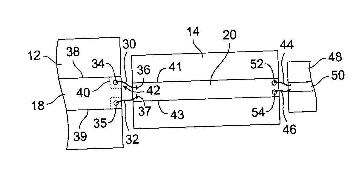
[0025] The present invention enables connecting one planar transmission device to a component, such as another planar transmission device or an electronic device, with improved impedance continuity. Most of the current in a planar transmission device flows on the surface and along the edges of conductive regions, such as along the edges of the center conductors of microstrip or co-planar transmission lines, and along the opposing edges of slotline transmission structures. Conventional methods of interconnecting a planar transmission device to a component often result in the current flow having to “bend” from the edge of the conductive region to the bond, which is believed to degrade impedance continuity.

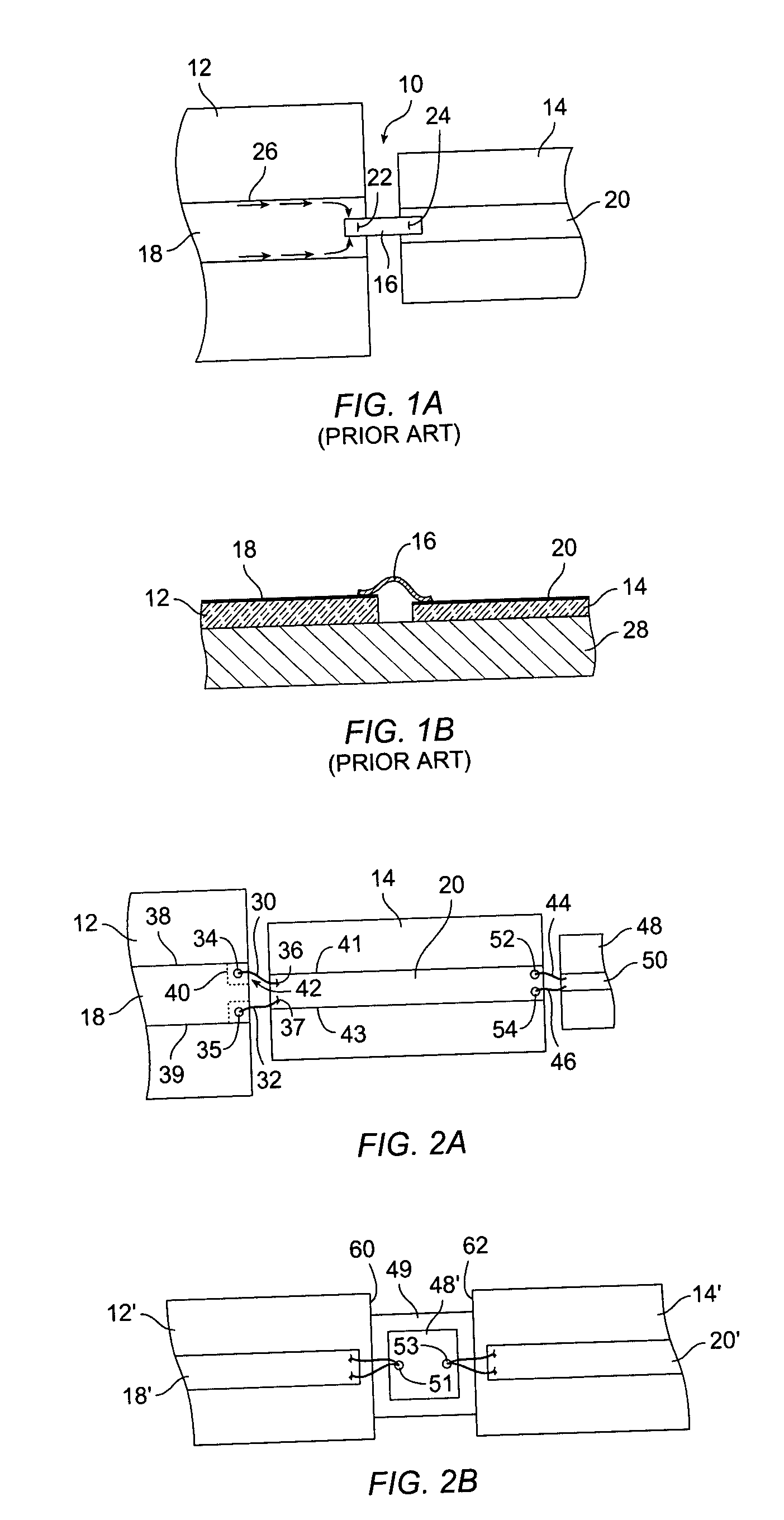
[0026]FIG. 1A shows a plan view of a prior art electrical interconnection 10 connecting a first microstrip transmission line 12 to a second microstrip transmission line 14. The electrical interconnection 10 includes a ribbon 16 bonded to center conductors 18, 20 of th...


PUM


Abstract

Wire bonds connect current-carrying edges of high-frequency planar conductors to other electrical devices. In one embodiment, planar transmission lines are interconnected using two wire bonds. One bond wire extends from an edge of a first center conductor to a corresponding edge of a second center conductor, and a second bond wire extends from the other edge of the first center conductor to the other edge of the second center conductor. Embodiments include center conductors at different heights and having different widths, and different electrical devices, such as semiconductor integrated circuits. In a particular embodiment, ball bonding is used. In some embodiments, a tack bond is included after a ball bond to allow closer attachment of the bond wire to the edge of the conductor.

Description

CROSS-REFERENCE TO RELATED APPLICATIONS [0001] Not applicable. STATEMENT REGARDING FEDERALLY SPONSORED RESEARCH OR DEVELOPMENT [0002] Not applicable. REFERENCE TO MICROFICHE APPENDIX [0003] Not applicable. FIELD OF THE INVENTION [0004] The present invention relates generally to interconnecting high-frequency electrical devices, and more particularly to using wire bonds on the edges of a planar high-frequency device to electrically connect to another high-frequency device. BACKGROUND OF THE INVENTION [0005] Microwave integrated circuits (“MICs”) typically consist of a number of separate high-frequency components, such as thin-film or thick-film transmission lines, semiconductor integrated circuits (“ICs”), active or passive electronic devices, and printed wiring boards (“PWBs”). MICs may also include surface-mount devices, integrated subcomponents, and grounding structures. The devices are electrically interconnected using a variety of techniques. [0006] Microstrip and coplanar trans...

Claims


Application Information

Patent Timeline
IPC IPC(8): H01P1/04
CPCH01L24/45H01L23/66H01L2224/45144H01L2224/4809H01L2224/4813H01L2224/48471H01L2224/48472H01L2224/49111H01L2224/49171H01L2224/4941H01L2224/78301H01L2924/01079H01L2924/14H01L2924/19041H01L2924/19107H01L2924/20751H01L2924/3011H01L2924/3025H01P1/047H01L2224/45015H01L24/49H01L24/48H01L2924/00014H01L2924/00H01L2224/45014
Inventor QIN, XIAOHUIAKINWANDE, DEJISTEPHENS, JAMES P.ZINMASTER, ROBINCLATTERBAUGH, JIM
Owner AGILENT TECH INC
Why Eureka
Try Eureka