Driver device for driving capacitive light emitting elements

a technology of capacitive light and driver device, which is applied in the direction of static indicating device, pulse technique, instruments, etc., can solve problems such as the risk of a faulty operation, and achieve the effects of reducing electrical power consumption, suppressing heat radiation, and increasing reliability

Inactive Publication Date: 2005-04-21
PANASONIC CORP
View PDF5 Cites 6 Cited by
  • Summary
  • Abstract
  • Description
  • Claims
  • Application Information

AI Technical Summary

Benefits of technology

[0017] One object of the present invention is to provide a driver device for driving capacitive light emitting elements that can achieve size reduction, increased reliability and reduced electrical power consumption while heat radiation is suppressed.

Problems solved by technology

Accordingly, when a certain type of image should be displayed, a resonance circuit that includes the capacitor C1, coils L1 and L2 and the load capacitor C0 of the PDP 10 enters the DC drive state and this creates the risk of a faulty operation due to the localized generation of heat, noise generation, and so forth.

Method used


Image

  • Driver device for driving capacitive light emitting elements
  • Driver device for driving capacitive light emitting elements
  • Driver device for driving capacitive light emitting elements

Examples


Embodiment Construction

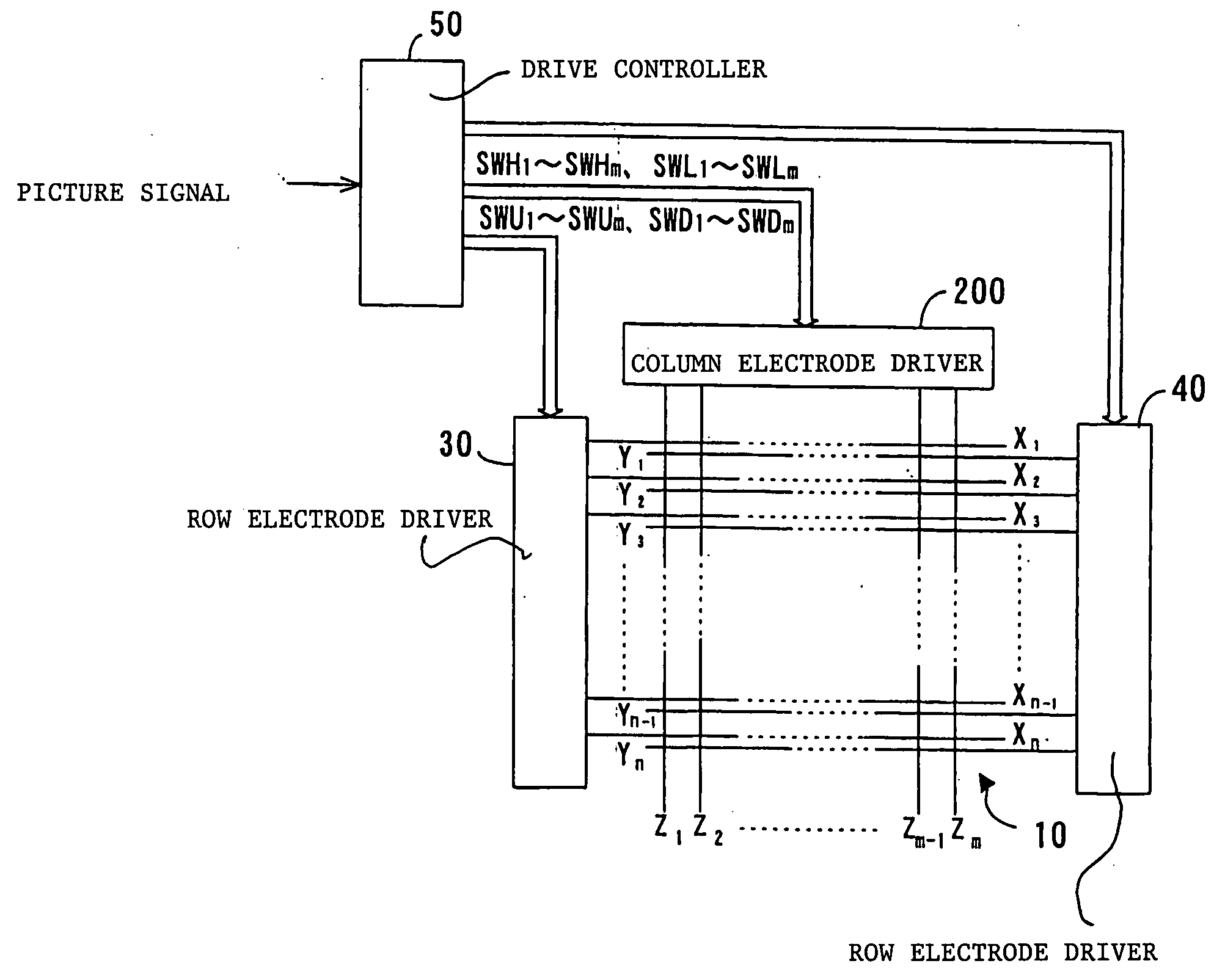
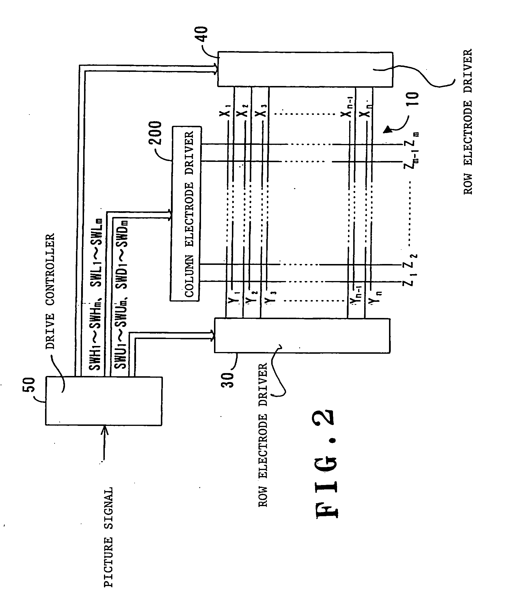
[0030] Referring to FIG. 2, a display device that adopts a PDP as a display panel having a plurality of capacitive light emitting elements will be described.

[0031] In FIG. 2, a PDP 10 includes a plurality of row electrodes Y1 to Yn and X1 to Xn, which are arranged to extend in the row (width) direction of the screen, and a plurality of column electrodes Z1 to Zm, which are arranged to extend in the column (height) direction of the screen. Discharge spaces (not shown) are interposed between the row electrodes Y1 to Yn and X1 to Xn and the column electrodes Z1 to Zm. The row electrodes Y1 to Yn and X1 to Xn are orthogonal to the column electrodes Z1 to Zm. A single display line is defined by a pair of row electrodes Xi and Yi. That is, n display lines consisting of first to nth display lines is formed in the PDP 10. Discharge cells are formed at the points of intersection between the display lines and the column electrodes Z. The discharge cells serve as pixels. That is, discharge ce...


PUM


Abstract

A device for driving capacitive light emitting elements includes a plurality of electrical charge recovery switches that send a current corresponding with an electrical charge, which has accumulated in a capacitor, individually to a plurality of drive electrodes connected to the respective capacitive light emitting elements. The electrical charge recovery switches also supply a current corresponding with the electrical charge that has accumulated in each of the capacitive light emitting elements to the capacitor individually via each of the drive electrodes. The driver device also includes a plurality of output buffers that apply a pixel-data-dependent voltage to the drive electrodes. It is determined, for each drive electrode, whether the voltage of the drive electrode has shifted from a high voltage to a low voltage or from a low voltage to a high voltage on the basis of the pixel data. If the voltage shift has occurred on the drive electrode concerned, the associated electric charge recovery switch is set to the ON state over a predetermined period. If no voltage shift has occurred, the electrical charge recovery switch is set to the OFF state.

Description

BACKGROUND OF THE INVENTION [0001] 1. Field of the Invention [0002] The present invention relates to a device for driving capacitive light emitting elements. [0003] 2. Description of the Related Art [0004] Display panels that include capacitive light emitting elements are often called capacitive display panels and marketed as wall-mounted TVs. Typical wall-mounted TVs are plasma display panels (hereinafter called ‘PDP’) and electroluminescence display panels (hereinafter called ‘ELDP’). [0005]FIG. 1 of the attached drawings shows part of a driver device that drives a capacitive display panel to emit light by applying a variety of drive pulses to the capacitive display panel. This driver device is disclosed in Japanese Patent Kokai (Laid-Open Application) No. 2002-156941. [0006] In FIG. 1, a PDP 10 has a plurality of row electrodes (not shown) and a plurality of column electrodes Z1 to Zm arranged to intersect one another. Discharge cells (not shown), which correspond with pixels, ar...

Claims


Application Information

Patent Timeline
Patent Type & Authority Applications(United States)
IPC IPC(8): H01L51/50G09G3/20G09G3/288G09G3/291G09G3/293G09G3/296G09G3/298G09G3/30H03K17/00H03K17/687H05B33/14
CPCG09G3/293G09G3/2965G09G2340/16G09G2330/021G09G2330/045G09G2310/066G09G3/296
Inventor IWAMI, TAKASHI
Owner PANASONIC CORP
Why Eureka
Try Eureka