Lithographic apparatus, device manufacturing method, and slide assembly

a technology of lithographic apparatus and slide assembly, which is applied in the direction of electrical apparatus, printing, instruments, etc., can solve the problems of unallowable inaccuracy in positioning of objects, conventional bearing systems configured to allow a slide member to move over a running surface without friction, and slide members to be heavy and large too. , to achieve the effect of reducing the manufacturing tolerance of the slide member, increasing the positive effect of the bearing system according to an embodiment of the invention, and reducing the manufacturing cos

Active Publication Date: 2005-04-21
ASML NETHERLANDS BV
View PDF7 Cites 6 Cited by
  • Summary
  • Abstract
  • Description
  • Claims
  • Application Information

AI Technical Summary

Benefits of technology

[0020] Embodiments of the invention include a lithographic apparatus which is provided with moveable slide members configured to carry one or more objects, which moveable slide members are configured to move over a running surface of a base without friction, which moveable slide members can reach higher acceleration levels and / or higher speeds while moving over the running surface than known slide members.
[0027] By arranging the first force generating device and the second force generating device of the bearing system in accordance with an embodiment of the invention, the design of the bearing system in accordance with an embodiment of the invention may be more compact than conventional designs. Therefore, the slide member according to an embodiment of the invention is smaller, and has less weight than known conventional slide members. Due to the reduction of the weight of the slide member, the slide member can achieve a higher level of acceleration and a higher speed compared to known slide members, without an increase of the current of the motor driving the slide member.
[0029] In the bearing system of the slide assembly in accordance with an embodiment of the invention, the point of action of the first force and the point of action of the second force are located closer to each other than in conventional bearing systems, which results in a reduction of the resultant bending moment induced onto the slide member by the bearing system. This may lead to an additional reduction of the weight of the slide member.
[0030] The first and the second force generating devices can even be arranged in such a way that the point of action of the first force and the point of action of the second force coincide. This way, there is even no resultant bending moment from the first and second force, so the positive effect of the bearing system according to an embodiment of the invention increases. This can be achieved by arranging the second force generating device in such a way that they encompass the first force generating device completely, and that they follow the outside contour of the first force generating device at a constant distance over the entire circumference.
[0031] Arranging the first force generating device and the second force generating device of the bearing system in accordance with an embodiment of the invention can reduce the manufacturing tolerances of the slide member as compared to conventional slide members. Since the first force generating device and the second force generating device of the bearing system in accordance with an embodiment of the invention are located on a single face of the slide member, it is no longer required to arrange two faces of the slide member accurately relative to each other. This reduces the manufacturing costs of the slide member.
[0035] According to yet another embodiment of the invention, ceramic material can be finished very even, which facilitates the control of the distance between the slide member and the running surface. In an embodiment, as a metal counter plate is provided on the surface, the materials of the running surface and the face of the slide member interacting with the running surface are very different. This results in very low adhesion between the slide member and the running surface if they come into sliding contact with each other, for example in case of a bearing system failure or unintended movement of the slide member when the bearing system is switched off. This low adhesion prevents (parts and / or particles of) the slide member and / or the bearing system from getting stuck to the running surface and the other way around due to cold welding.

Problems solved by technology

The stiffness of this gas film during operation is a relevant parameter in the dynamic behavior of the slide member, especially with regard to the vibrations of the slide member, which vibrations may give rise to unallowable inaccuracies in positioning of objects carried by the slide member.
Conventional bearing systems configured to allow a slide member to move over a running surface without friction are generally heavy and large.
As conventional bearing systems are mounted at least partly in the slide member, they generally cause the slide members to be heavy and large too.
This may be disadvantageous, since new developments ask for faster moving slide members with higher acceleration levels, while the maximum allowable motor current in the motor that drives the slide member is limited.

Method used


Image

  • Lithographic apparatus, device manufacturing method, and slide assembly
  • Lithographic apparatus, device manufacturing method, and slide assembly
  • Lithographic apparatus, device manufacturing method, and slide assembly

Examples


Embodiment Construction

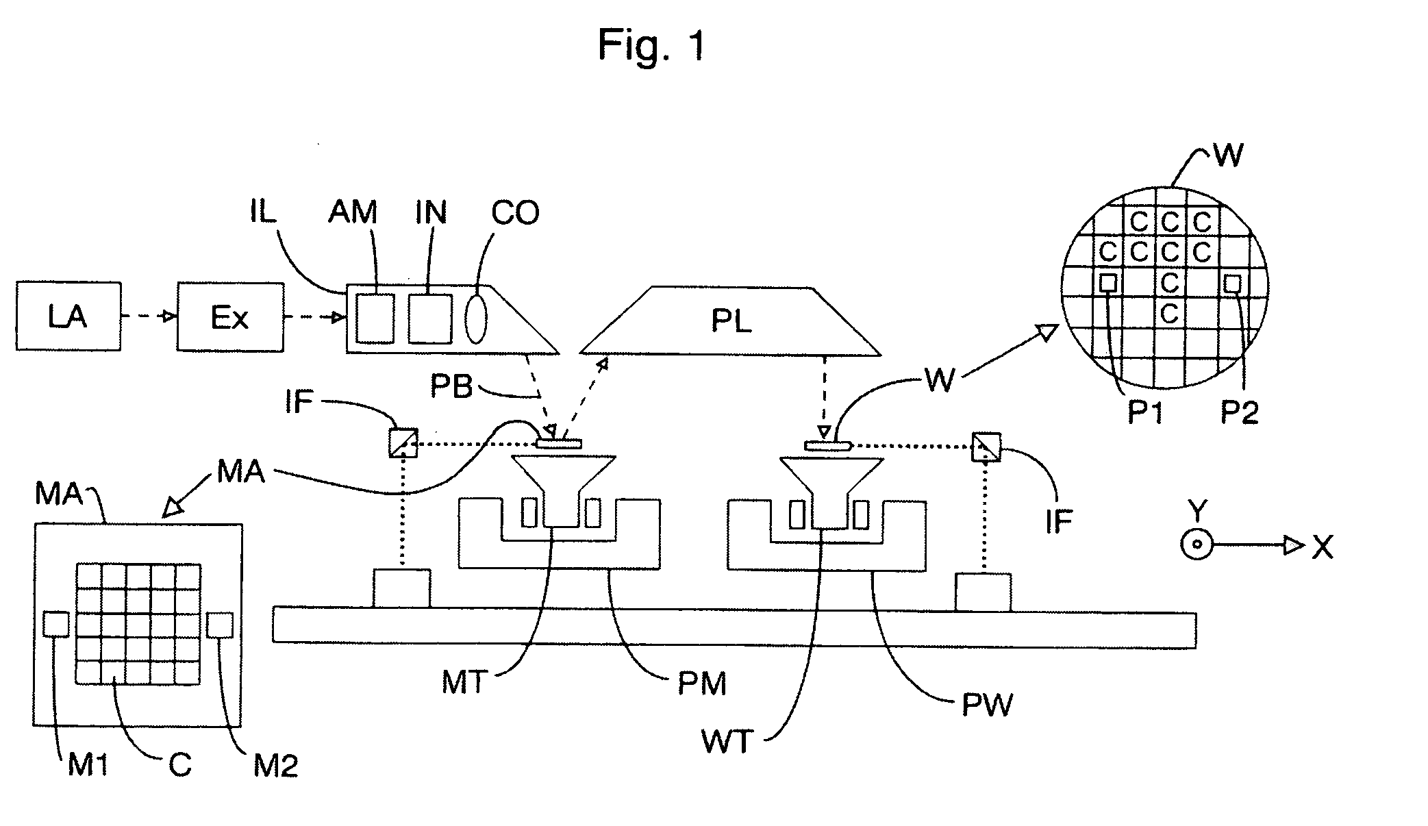
[0059]FIG. 1 schematically depicts a lithographic apparatus according to an embodiment of the invention. The apparatus includes a radiation system Ex, IL, configured to supply a beam PB of radiation (e.g. laser radiation). In this particular case, the radiation system also includes a radiation source LA. The apparatus also includes [0060] a first object table (mask table) MT provided with a mask holder configured to hold a mask MA (e.g. a reticle), and connected to a first positioning device PM configured to accurately position the mask with respect to the projection system (“lens”), item PL. The apparatus further includes a second object table (substrate table) WT provided with a substrate holder configured to hold a substrate W (e.g. a resist-coated silicon wafer), and connected to a second positioning deviceW configured to accurately position the substrate with respect to the projection system (“lens”), item PL, the projection system (“lens”) PL being configured to image an irrad...


PUM

PropertyMeasurementUnit
wavelengthaaaaaaaaaa

Abstract

The invention relates to a lithographic apparatus which includes a slide assembly, having a base, which base has a running surface, a slide member adapted to move over the running surface, and a bearing system configured to create a distance between the slide member and the running surface. The bearing system includes a first force generating device configured to provide a first force in a first direction, the first direction being substantially perpendicular to the running surface, and a second force generating device configured to provide a second force in a second direction, the second force being opposite to the first direction. The first and second force generating devices are adapted to co-operate in establishing the distance between the slide member and the running surface. The second force generating device includes a plurality of force generating elements defining an area between them, in which area the first force generating device is arranged.

Description

PRIORITY INFORMATION [0001] This application claims priority from European Patent Application No. 03077687.6, filed Aug. 27, 2003, the contents of which is herein incorporated by reference in its entirety BACKGROUND [0002] 1. Field of the Invention [0003] The present invention relates to lithographic apparatus and methods [0004] 2. Description of the Related Art [0005] The term “patterning structure” as here employed should be broadly interpreted as referring to a structure that can be used to endow an incoming radiation beam with a patterned cross-section, corresponding to a pattern that is to be created in a target portion of the substrate. Generally, the pattern will correspond to a particular functional layer in a device being created in the target portion, such as an integrated circuit or other device (see below). Examples of such patterning structure include: [0006] A mask. The concept of a mask is well known in lithography, and it includes mask types such as binary, alternati...

Claims


Application Information

Patent Timeline
Patent Type & Authority Applications(United States)
IPC IPC(8): G03F7/20H01L21/027
CPCG03F7/70816
Inventor HAGE, EDWARD
Owner ASML NETHERLANDS BV
Why Eureka
Try Eureka