Illumination structure with multiple light sources and light integration device in a projection system

Inactive Publication Date: 2005-04-21
DELTA ELECTRONICS INC
View PDF2 Cites 22 Cited by
  • Summary
  • Abstract
  • Description
  • Claims
  • Application Information

AI Technical Summary

Benefits of technology

[0023] From the foregoing descriptions, according to the illumination structure with multiple light sources in a projection system, the light beams from the lamps, which serve as the light sources, can be directly focused onto the light incident surface of the integration rod, the condenser lens can be saved. This can reduce the volume of the projection system, but also does not produce aberration. IN addition, since the light is directly f

Problems solved by technology

During processing several conversions of image signals between digital and analog, the distortion of image inevitably occurs.
This illumination structure has several defects.
Due to the use of the condenser lens 15 in the conventional illumination structure, the emitted light cannot be completely focused onto one point, and therefore the issue of spherical aberration occurs.
The aberration issue causes the increase of a spot, and the efficiency for using the light source gets worse.
However, since the cross-sectional area at the entrance of the integration rod 25 is reduced, then the light coupling efficiency is relatively reduced.
How

Method used


Image

  • Illumination structure with multiple light sources and light integration device in a projection system
  • Illumination structure with multiple light sources and light integration device in a projection system
  • Illumination structure with multiple light sources and light integration device in a projection system

Examples


Embodiment Construction

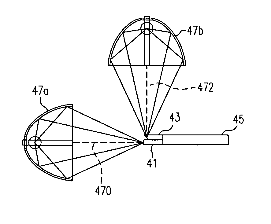
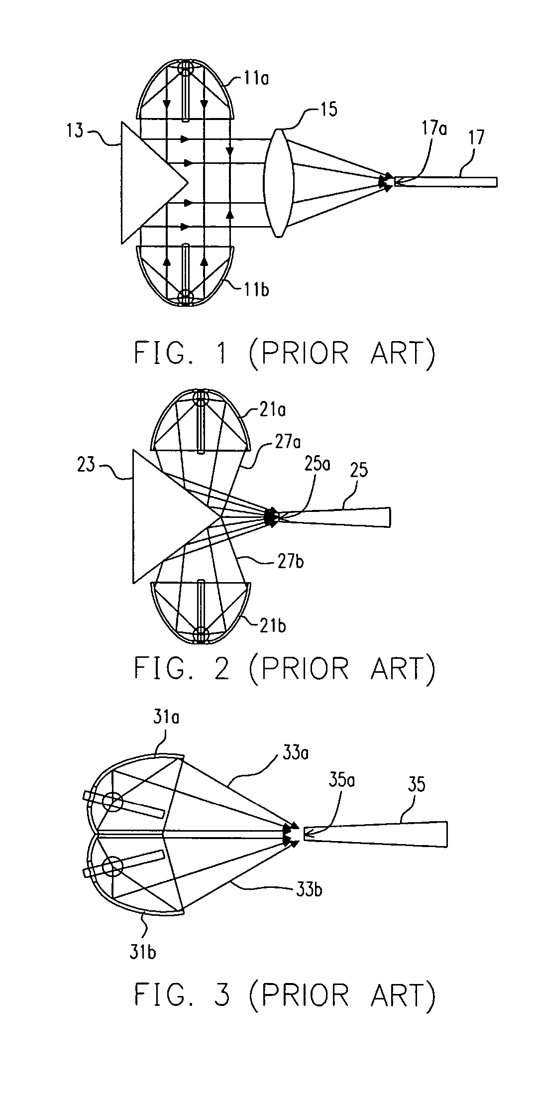
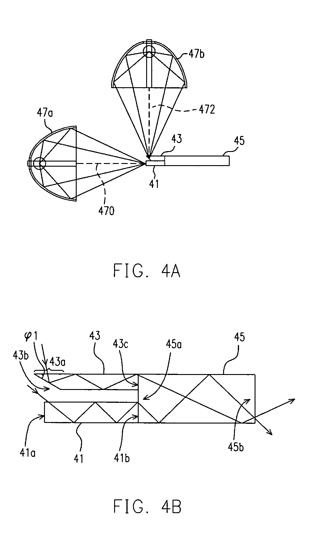
[0036] The illumination structure with multiple light sources of a projection system in the invention mainly uses three integration rods in place of the conventional design with one integration rod. The advantage is that the light beams emitted from the lamps can be directly focused onto the integrations rod and it is not necessary to have the cutting-angle design on the lamp housing. The light beam emitted from each lamp can pass an integration rod, and then further collected by the third integration rod. After the total internal reflections for getting uniform, the light beams are led out from the integration rod. In the following embodiment, the longitudinal direction is defined as the direction of the longer optical axis of the integration rod, that is, the traveling direction of the light in the integration rod.

[0037]FIG. 4A is a drawing, schematically illustrating an illumination structure with multiple light sources of projection system, according to a preferred embodiment o...


PUM


Abstract

An illumination structure with multiple light sources in projector has first, second, third integration rods, first and second light sources. The second integration rod having a light incident surface, a light outgoing surface and a light reflection surface, is placed along the first integration rod. The light incident surface is parallel to the second integration rod, forming an angle between the light incident surface and light reflection surface. The first light source is vertically placed with respect to the second light source. The light emitted from the first light source is focused to the light incident surface of the first integration rod. The light emitted from the second light source is incident to the light incident surface of the second integration rod, and then reflected by the light reflection surface. The light reflected by the light reflection surface propagates forward the light outgoing surface of the second integration rod.

Description

CROSS-REFERENCE TO RELATED APPLICATION [0001] This application claims the priority benefit of Taiwan application serial no. 92128258, filed on Oct. 13, 2003. BACKGROUND OF THE INVENTION [0002] 1. Field of Invention [0003] The present invention relates to an illumination structure of projection system system. More particularly, the present invention relates to a projection system with multiple light sources and light integration device. [0004] 2. Description of Related Art [0005] The digital light processing (DLP) projection system is a projecting system designed under an almost new concept, in which the image from the DLP projection system is processed. The rather conventional digital liquid-crystal (LC) projection system is also in digital manner. However, it is done by respectively projecting three-color image signals from the red, green, and blue LC panels to being overlapping on the screen, and then the color image is displayed due to the effect of light overlapping. In the digi...

Claims


Application Information

Patent Timeline
IPC IPC(8): F21V8/00G02B6/42G02B6/00G02B6/28G02F1/133G03B21/00G03B21/14H01L27/146H01L27/148
CPCG02B6/0018G02B6/0068H01L27/14625G02B6/4298G02B6/2808
Inventor YEH, HSIN-TSUNGCHENG, RICEHUANG, JUNEJEI
Owner DELTA ELECTRONICS INC
Why Eureka
Try Eureka