Adjustable resistance valve for a cerebrospinal fluid shunt system

a cerebrospinal fluid and resistance valve technology, applied in the direction of wound drains, biocide, plant ingredients, etc., can solve the problems of hyperdrainage leading to subnormal intracranial pressure, unanticipated, and the siphoning effect and the unknown peritoneal pressure change, and achieve the effect of simple construction

Inactive Publication Date: 2005-04-21
MEDOSA
View PDF10 Cites 19 Cited by
  • Summary
  • Abstract
  • Description
  • Claims
  • Application Information

AI Technical Summary

Benefits of technology

[0012] The aim of the present invention is to remedy the inconveniences of the current systems by providing an adjustable resistance valve adapted to be integrated into a shunt system for the treatment of hydrocephalus, the resistance to CSF flow of the valve being adjustable non-invasively after implantation, the range of resistance to CSF flow covering the necessities of all possible resorption sites and the device being of simple construction.
[0013] Therefore, an object of the present invention is to provide an adjustable resistance valve for a cerebrospinal fluid shunt system including an actuator for allowing the selection of the resistance to flow of the valve. A device is provided for selecting at least one passage across the valve. A resistance system including a set of passages each defining a different resistance to flow is also included. These passages are disposed in a circle facing the selecting device, such as to guide the flow of the cerebrospinal fluid traversing the at least one passage of the selecting device through the selected passage of the resistance system. The actuator enables changing the relative position of the selecting device with respect to the resistance system by a rotational movement to select the desired resistance of the valve.
[0014] Another object of the present invention is to provide a cerebrospinal fluid shunt system incorporating an adjustable resistance valve having a proximal catheter to be introduced in the ventricles of the brain and allowing the draining of cerebrospinal fluid from the ventricles. A distal catheter is introduced in a distal resorption site such as the atrium, the peritoneum or the sagittal sinus and allowing drainage of cerebrospinal fluid into this site. A main body of the shunt is connected at one end to the proximal catheter and at the other end to the distal catheter. The main body houses an adjustable resistance valve comprising an actuator allowing the selection of the resistance to flow of the valve, with means for selecting at least one passage across the valve. The resistance system includes a set of passages each defining a different resistance to flow. The passages are disposed in a circle facing the selecting device such as to allow the flow of the cerebrospinal fluid traversing the at least one passage of the selecting device through the selected passage of the resistance system. The actuator enables changing the relative position of the selecting device with respect to the resistance system by a rotational movement to select the desired resistance of the valve.

Problems solved by technology

Hydrocephalus is currently treated by either restoring the physiological CSF pathway by endoscopy, a method which can only be applied under certain conditions and which is limited in its success primarily by a high probability of re-obstruction of the natural pathway, or by derivation of the excess of CSF into a remote resorption site by using artificial means called shunt, thus restoring the normal physiological value of the intracranial pressure.
The main drawbacks of these devices are the so called siphoning effect and the unknown peritoneal pressure changes.
This inherits the danger of hyperdrainage leading to subnormal intracranial pressure.
Therefore, it is impossible to anticipate the intracranial pressure, even if the opening pressure of the shunt is known, thus making it impossible for the surgeon to select the correct opening pressure a priori.
These devices are in principle insensitive to the siphoning effect, but inherit the problem of necessitating access to atmospheric pressure.
Due to its fixed resistance the device cannot be fine tuned to the individual needs of a patient, i.e. after implementation it doesn't allow the surgeon to fit the resistance of the derivation circuit to match the resistance of the normal CSF resorption pathway of a specific pathway.
Also, due to its very limited range in resistance to flow around 10 mm Hg / ml / min, the proposed device is limited to a treatment of hydrocephalus using the sagittal sinus as resorption site.

Method used


Image

  • Adjustable resistance valve for a cerebrospinal fluid shunt system
  • Adjustable resistance valve for a cerebrospinal fluid shunt system
  • Adjustable resistance valve for a cerebrospinal fluid shunt system

Examples


Embodiment Construction

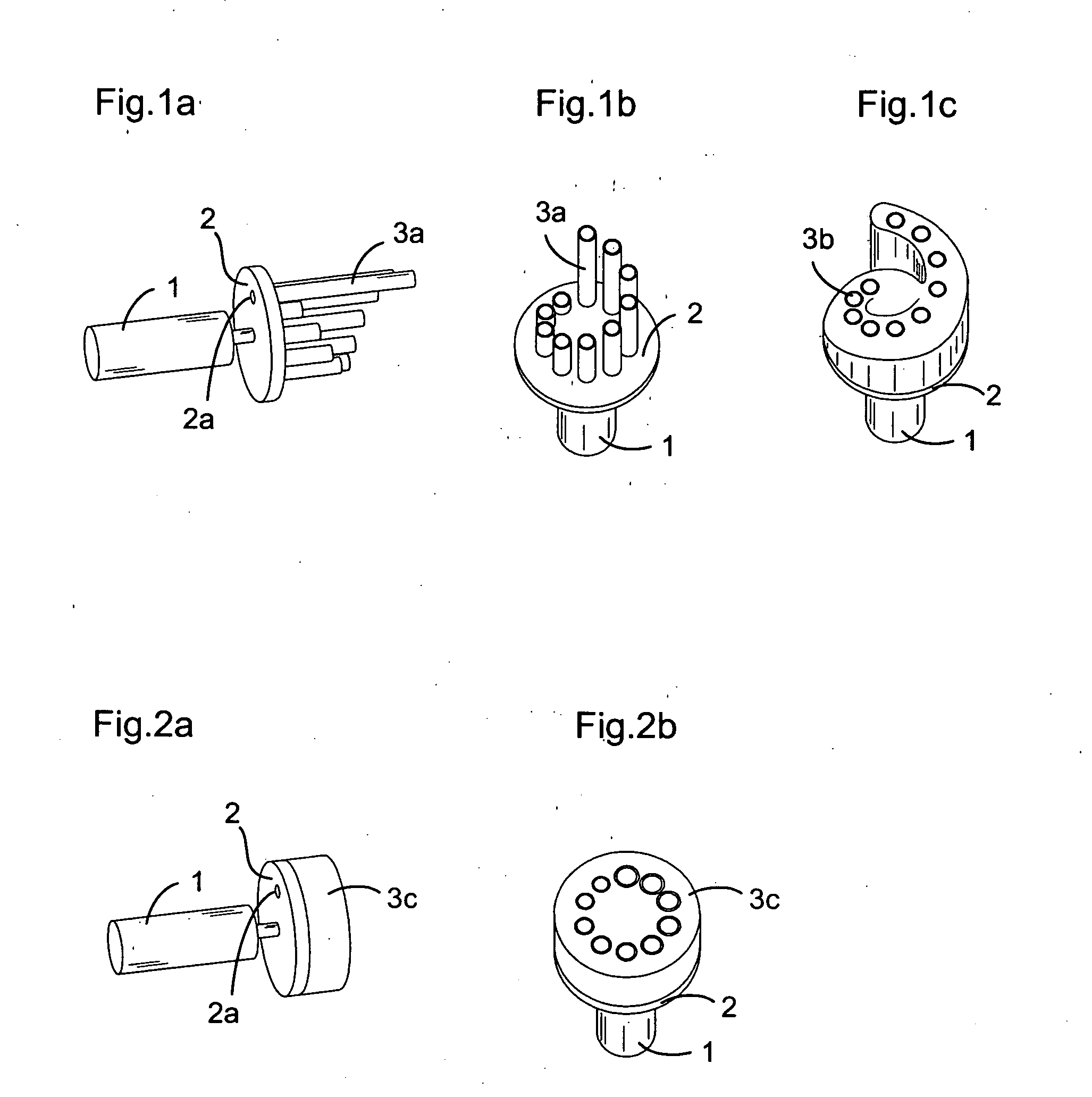
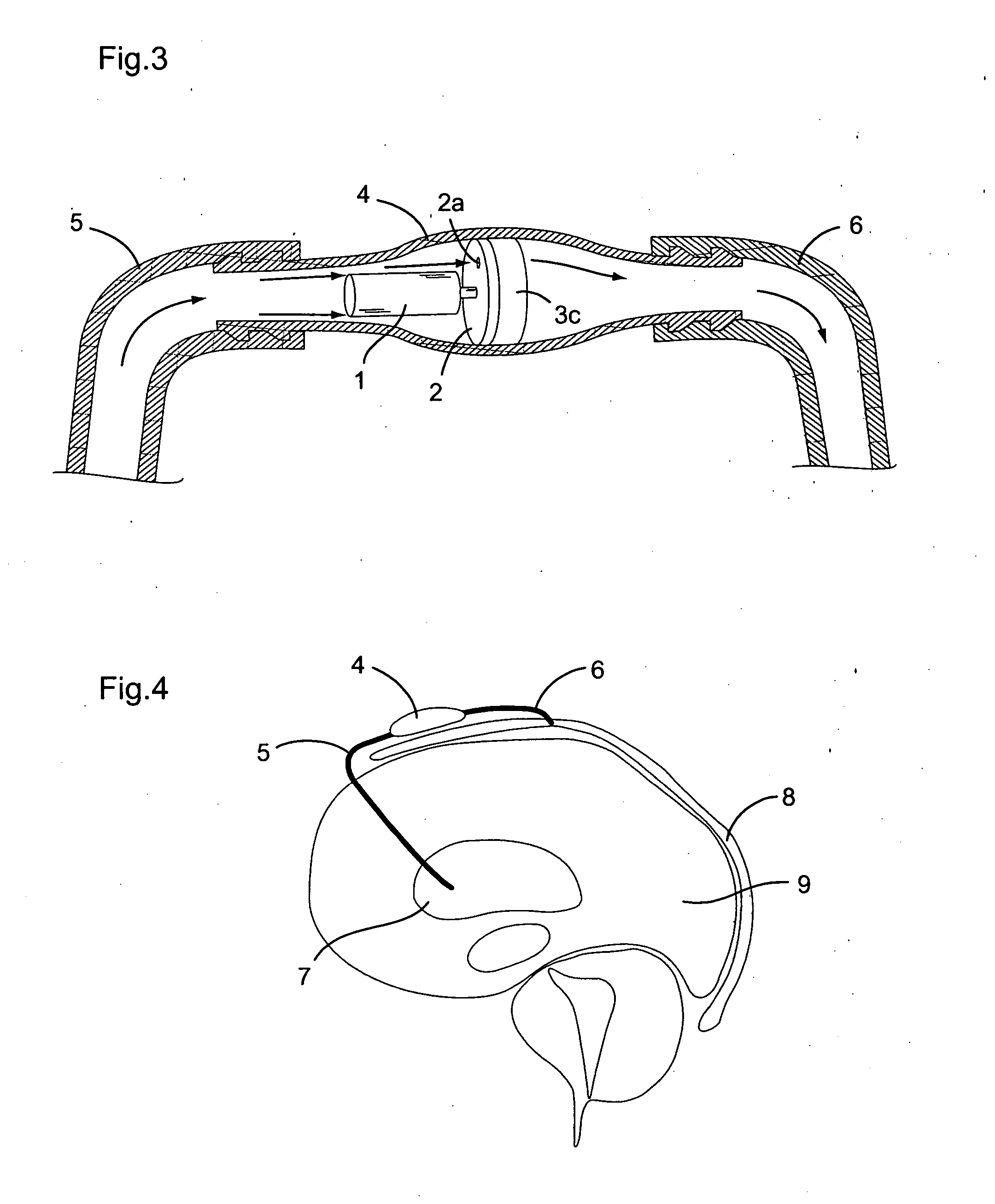
[0023] The invention will now be described in detail with reference to the annexed figures which are illustrating by way of example several embodiments of the invention.

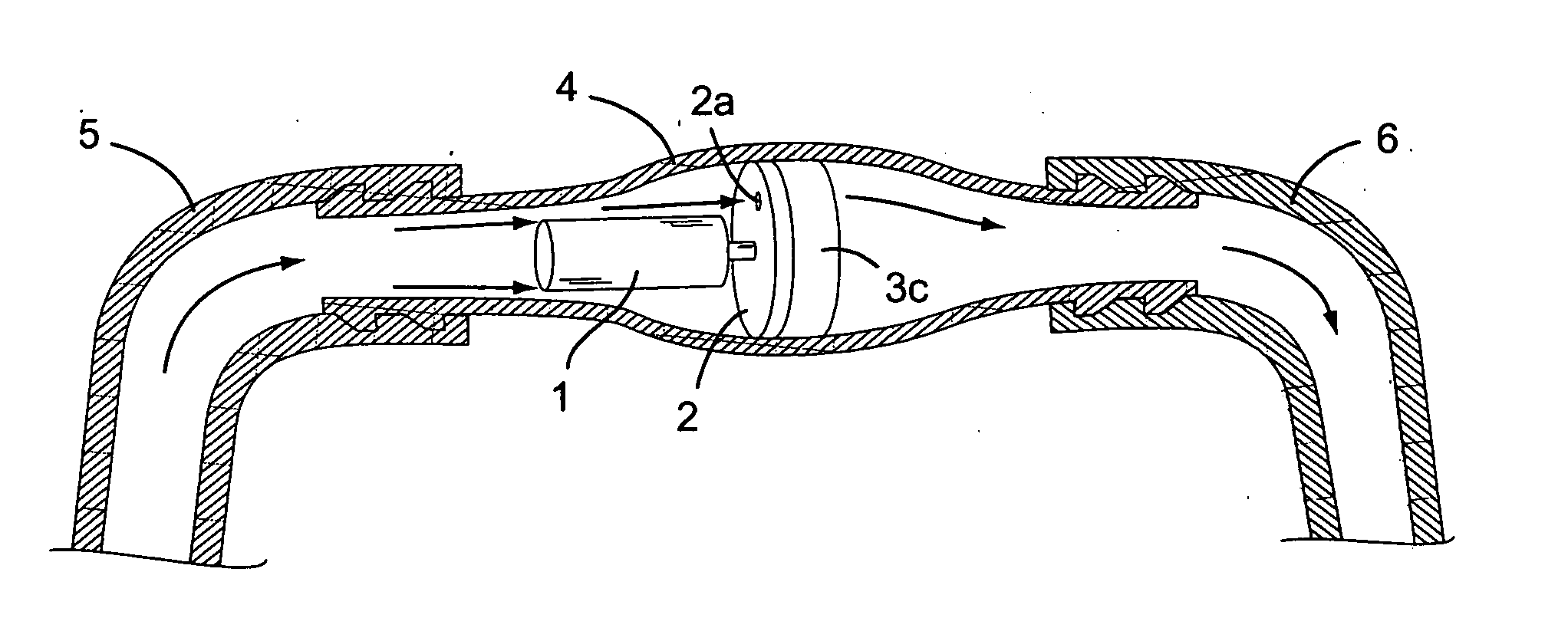
[0024] An adjustable resistance valve for a cerebrospinal fluid shunt system according to the present invention comprises, like illustrated in FIGS. 1a to 1c and 2a to 2b, an actuator 1 allowing the selection of the resistance to flow of the valve, and selecting means 2 with at least one passage 2a traversing these selecting means. A preferential realization of such selecting means is a disc 2 with at least one passage 2a traversing the disc near its periphery in a direction parallel to its longitudinal axis. Furthermore, an adjustable resistance valve according to the present invention comprises a resistance system 3 comprising a set of passages defining each a different resistance to flow, the passages being situated around a circle facing the selecting means 2 such as to guide the flow of the cerebrospinal fluid ...


PUM


Abstract

An adjustable resistance valve for a cerebrospinal fluid shunt system includes an actuator for allowing the selection of the resistance to flow of the valve, a device for selecting at least one passage traversing across the valve, and a resistance system. The resistance system includes a set of passages each defining a different resistance to flow. The passages are disposed in a circle facing the selecting device such as to guide the flow of the cerebrospinal fluid traversing the passage of the selecting device through the selected passage of the resistance system. The actuator enables one to change the relative position of the selecting device with respect to the resistance system by a rotational movement to select the desired resistance of the valve.

Description

1. FIELD OF THE INVENTION [0001] The present invention relates to an adjustable resistance valve adapted to be used within a shunt system for the treatment of hydrocephalus as well as a cerebrospinal fluid shunt system itself. Additionally, the present invention relates to a method of treatment of hydrocephalus using the adjustable resistance valve and to a method method of treatment of hydrocephalus using the cerebrospinal fluid shunt system. 2. DISCUSSION OF THE RELATED ART [0002] In the ventricular system of the brain the so called cerebrospinal fluid (CSF) is formed at a given formation rate. This formation happens regardless of the intracranial pressure exerted on the brain by the cerebrospinal fluid, this latter normally being evacuated at a certain flow rate into the sagittal sinus as the natural CSF resorption site. In case of an obstruction along the natural cerebrospinal fluid pathway, which starts at the level of the ventricles of the brain situated in the middle of the c...

Claims


Application Information

Patent Timeline
Patent Type & Authority Applications(United States)
IPC IPC(8): A61M1/00A61M27/00
CPCA61M27/006
Inventor GINGGEN, ALECTARDY, YANIK
Owner MEDOSA
Why Eureka
Try Eureka