
System and method for malicious code detection

a malicious code and detection system technology, applied in the field of computer security, can solve the problems of not having a single anti-virus scanner that is 100% coverage of known viruses, unable to detect malicious code quickly, etc., to achieve the effect of reducing the latency of content scanning and reducing overhead

Inactive Publication Date: 2005-04-21
RAKUTEN GRP INC
View PDF18 Cites 91 Cited by
  • Summary
  • Abstract
  • Description
  • Claims
  • Application Information

AI Technical Summary

Benefits of technology

[0010] These and other needs are addressed by the present invention, in which incoming content scanned in parallel by different anti-virus software on separate processors in a multi-processor or multi-computer configuration. By scanning incoming content in parallel on separate processors, the latency of scanning the content is reduced to that of

Problems solved by technology

A non-damaging virus is still a virus, yet even non-damaging viruses are considered malicious if they consume valuable computer resources without permission.
The recent, explosive growth of the Internet has increased the opportunities for spreading malicious code quickly throughout the world, for example, through infected files attached to electronic mail messages.
There are a large variety of viruses and other kinds of malicious code thriving on the Internet, but no single anti-virus scanner has 100% coverage of the known viruses.
Therefore, incomplete coverage of known viruses is a problem with individual anti-virus scanners.
Otherwise, the email is quarantined for 30 days and then destroyed.
This approach, however, suffers from several disadvantages, particularly in terms of latency.
Latency is the delay imposed by scanning for viruses.
Although a 1.2 second latency may appear to be small at first blush, it is unacceptably large for interactive traffic such as surfing the World Wide Web.
If a user had to wait 1.2 seconds every time to see a new web page, the user would quickly become frustrated and seek less secure ways of accessing the Internet.

Method used


Image

  • System and method for malicious code detection
  • System and method for malicious code detection
  • System and method for malicious code detection

Examples


Embodiment Construction

[0021] A system, method, and software for malicious code detection are described. In the following description, for the purposes of explanation, numerous specific details are set forth in order to provide a thorough understanding of the present invention. It will be apparent, however, to one skilled in the art that the present invention may be practiced without these specific details. In other instances, well-known structures and devices are shown in block diagram form in order to avoid unnecessarily obscuring the present invention.

[0022] Malicious Code Detection System

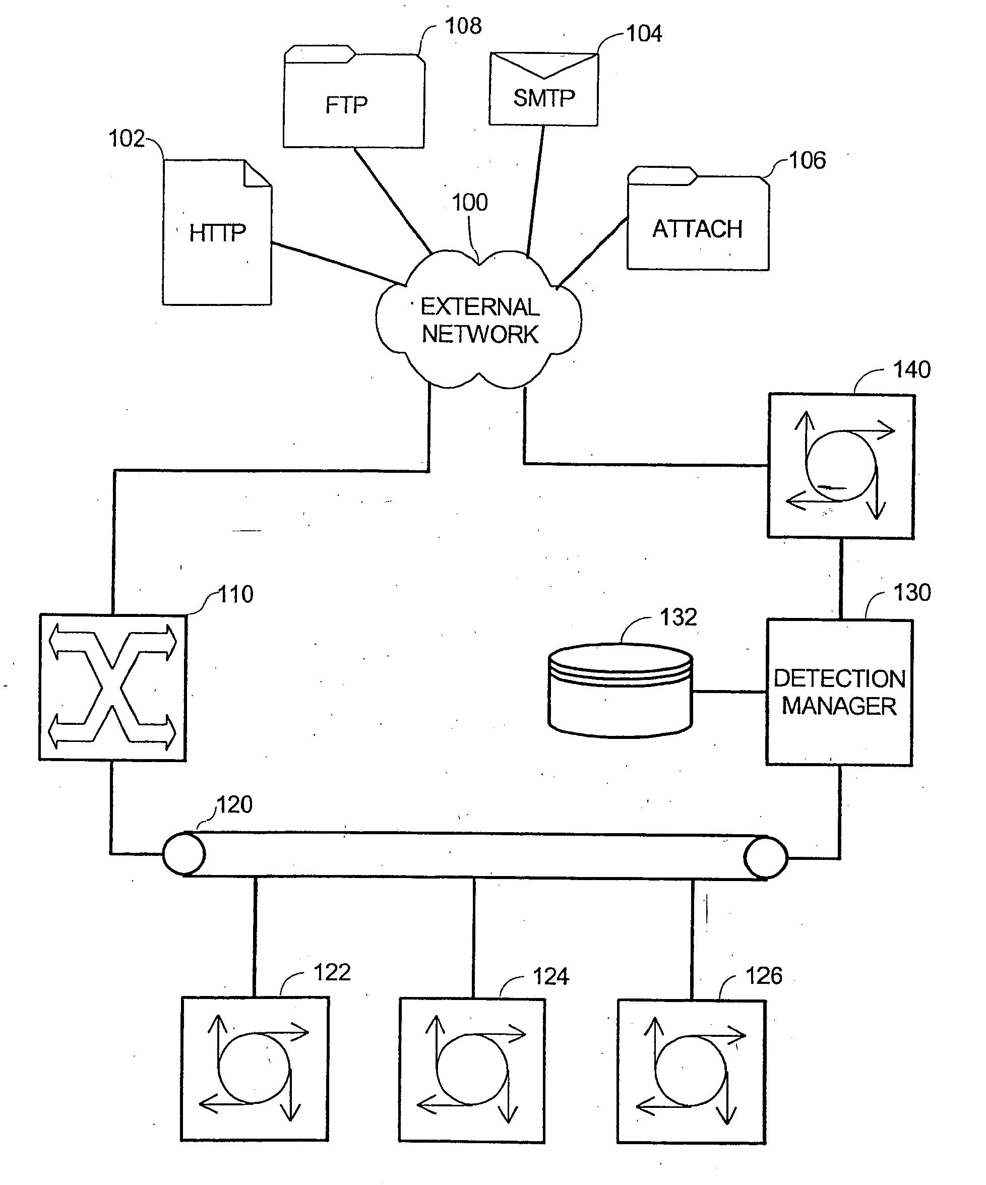
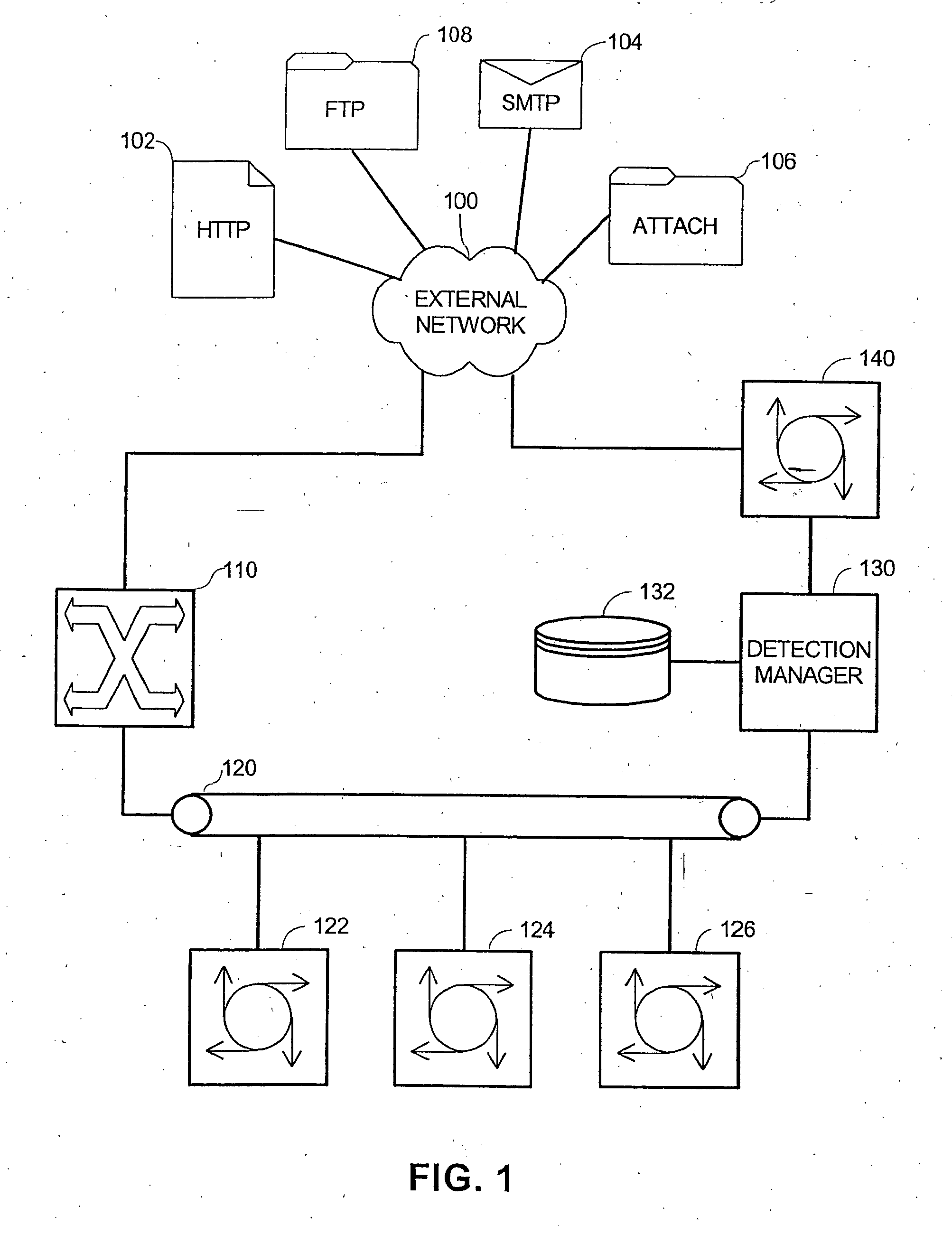
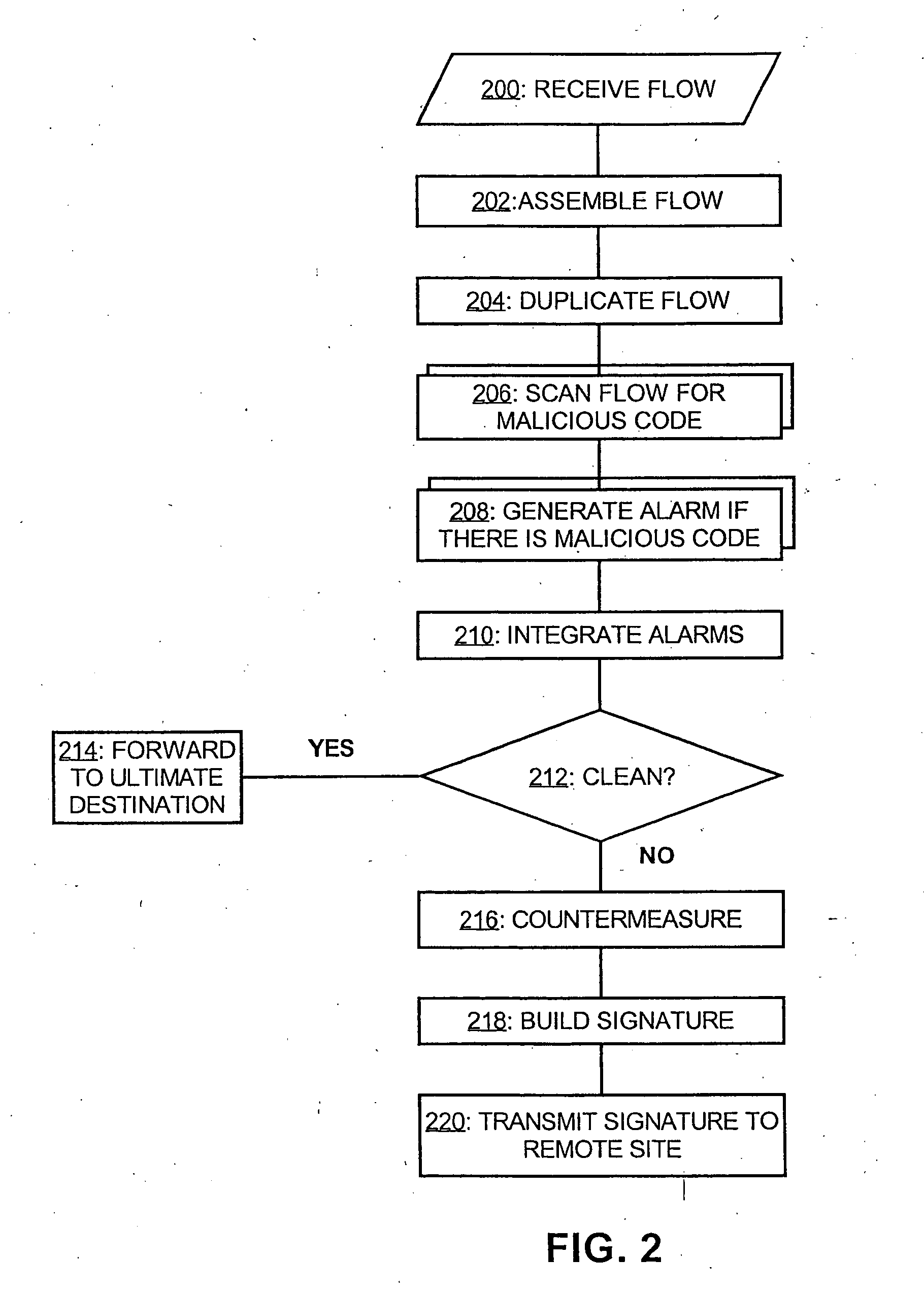
[0023]FIG. 1 depicts one embodiment of a malicious code detection system in accordance the present invention, whose operation is described in conjunction with FIG. 2. The malicious code detection system, which is suitable for deployment by Internet Service Providers (ISPs), network service providers, and corporate information systems departments for responsible for the employees' email and web browsing, is coupled t...


PUM


Abstract

A system for malicious code detection includes a front-end processor, multiple scanning computer systems, and a detection management system. During operation, the multiple scanning computer systems scan content for malicious code and generate an alarm when the content contains malicious code. The front-end processor receives a flow of content from an external network and distributes copies of the flow to each of the multiple scanning computer systems in parallel for scanning. The detection management system employs a countermeasure on the flow if at least one of the scanning computer systems generates the alarm.

Description

FIELD OF THE INVENTION [0001] The present invention relates to computer security and more particularly to a system and method for malicious code detection. BACKGROUND OF THE INVENTION [0002] Malicious code is software that is designed to damage a computer system or its data or to prevent the computer system from being used in its normal manner. Also termed “malware,” malicious code includes viruses, Trojan horses, worms, and malicious active content. A virus is a particularly pernicious kind of malicious code, capable of attaching itself to disks or other files and replicating itself repeatedly, typically without user knowledge or permission. Some viruses display symptoms, and some viruses damage files and computer systems, but neither symptoms nor damage is essential in the definition of a virus. A non-damaging virus is still a virus, yet even non-damaging viruses are considered malicious if they consume valuable computer resources without permission. [0003] Some viruses propagate ...

Claims


Application Information

Patent Timeline
IPC IPC(8): G06F21/00H04L29/06
CPCH04L63/145G06F21/567
Inventor HOEFELMEYER, RALPH S.PHILLIPS, THERESA E.
Owner RAKUTEN GRP INC
Learn More