Composite and method of manufacturing the same

a carbon nanotube and composite technology, applied in the direction of metal/metal-oxide/metal-hydroxide catalysts, energy input, synthetic resin layered products, etc., can solve the problems of poor electrical conductivity, poor rough carbon nanotube network, etc., to achieve excellent electrical and physical characteristics, excellent mechanical strength and thermal conductivity, and high electrical conductivity

a carbon nanotube and composite technology, applied in the direction of metal/metal-oxide/metal-hydroxide catalysts, energy input, synthetic resin layered products, etc., can solve the problems of poor electrical conductivity, poor rough carbon nanotube network, etc., to achieve excellent electrical and physical characteristics, excellent mechanical strength and thermal conductivity, and high electrical conductivity

US20050087726A1Inactive Publication Date: 2005-04-28FUJIFILM BUSINESS INNOVATION CORP

Image

  • Composite and method of manufacturing the same
  • Composite and method of manufacturing the same
  • Composite and method of manufacturing the same

Examples


example 1

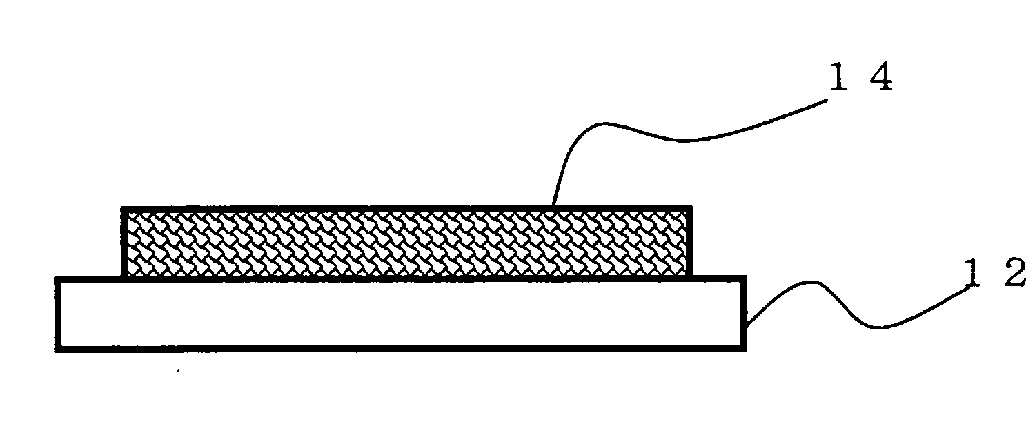
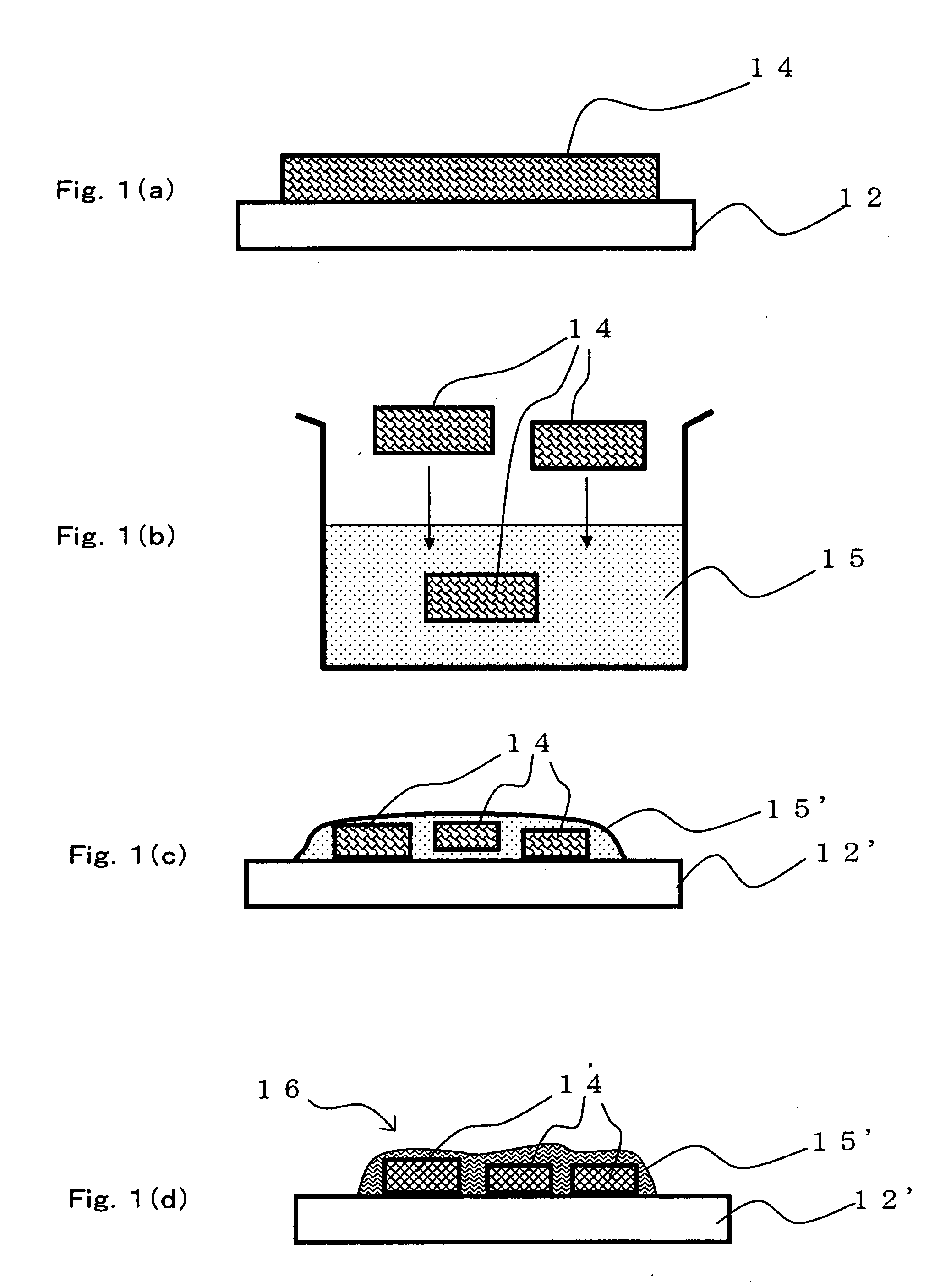
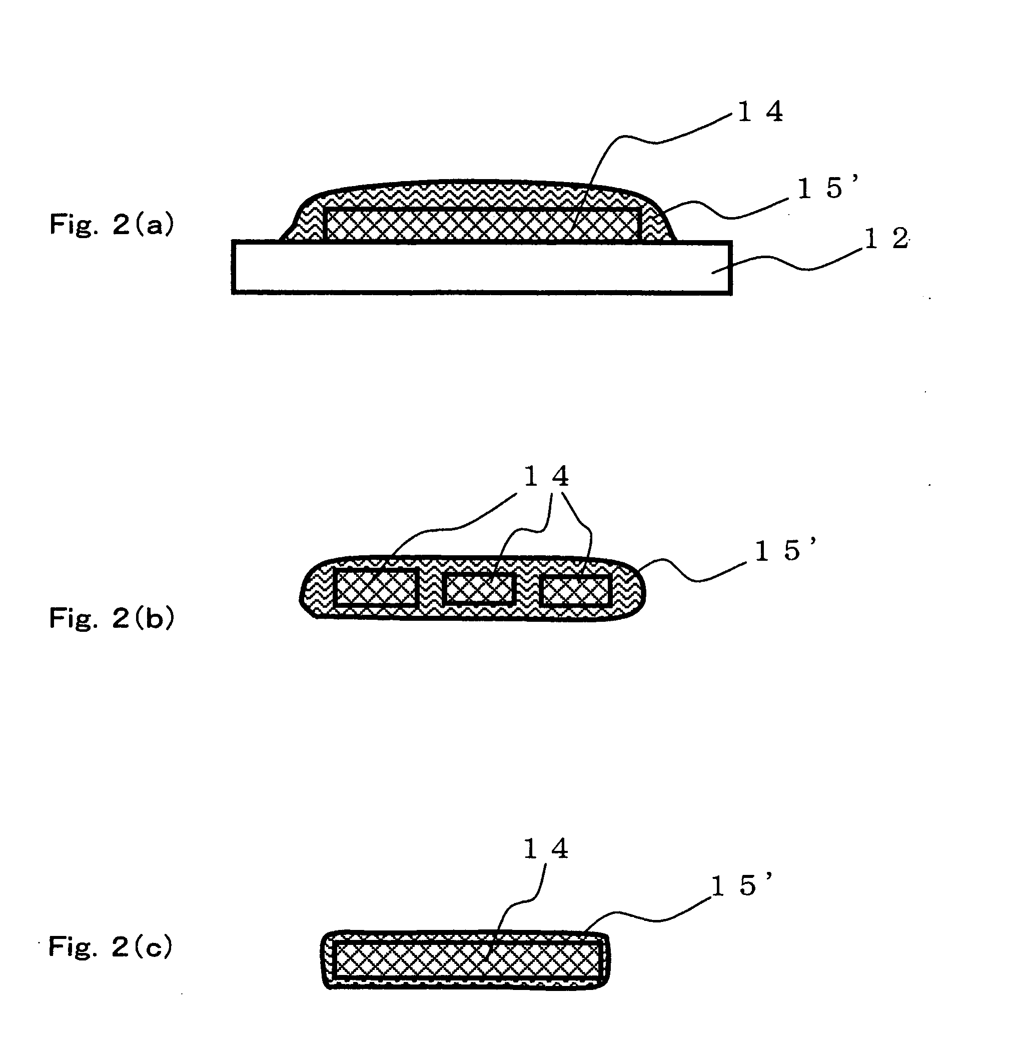
[0213] A composite was manufactured in accordance with the flow of the method of manufacturing a composite shown in FIGS. 1(a) to 1(d). The description of Example 1 uses the reference numerals shown in FIGS. 1(a) to 1(d) in some cases.

(A) Supplying Step

(A-1) Preparation of Cross-Linking Solution (Addition Step)

(i) Addition of Carboxyl Group . . . Synthesis of Carbon Nanotube Carboxylic Acid

[0214] 30 mg of multi-wall carbon nanotube powder (purity: 90%, average diameter: 30 nm, average length: 3 μm, available from Science Laboratories, Inc.) were added to 20 ml of concentrated nitric acid (a 60 mass % aqueous solution, available from Kanto Kagaku) for reflux at 120° C. for 20 hours, to synthesize carbon nanotube carboxylic acid. A reaction scheme of the above is shown in FIG. 3. In FIG. 3, a carbon nanotube (CNT) portion is represented by two parallel lines (the same applies for other figures relating to reaction schemes).

[0215] The temperature of the solution was returned to...


PUM

PropertyMeasurementUnit
diameteraaaaaaaaaa
current densityaaaaaaaaaa
Young's moduliaaaaaaaaaa

Abstract

Provided are: a composite formed by mixing a carbon nanotube structure and a metal-containing material, the carbon nanotube structure having a network structure constructed by mutually cross-linking functional groups bonded to plural carbon nanotubes through chemical bonding of the functional groups together; and a method of manufacturing the same. The composite of the carbon nanotube and the metal-containing material is capable of effectively using characteristics of the carbon nanotube structure.

Description

FIELD OF THE INVENTION AND RELATED ART STATEMENT [0001] The present invention relates to a composite of a carbon nanotube structure and a metal-containing material, and to a method of manufacturing the same. [0002] Carbon nanotubes (CNTs), with their unique shapes and characteristics, are being considered for various applications. A carbon nanotube has a tubular shape of one-dimensional nature which is obtained by rolling one or more graphene sheets composed of six-membered rings of carbon atoms into a tube. A carbon nanotube which is formed from one graphene sheet is called a single-wall carbon nanotube (SWNT) while a carbon nanotube which is formed from multiple graphene sheets is called a multi-wall carbon nanotube (MWNT). SWNTs are about 1 nm in diameter whereas multi-wall carbon nanotubes measure several tens nm in diameter, and both are far thinner than their predecessors, which are called carbon fibers. [0003] One of the characteristics of carbon nanotubes resides in that the...

Claims


Application Information

Patent Timeline
28 Apr 2005
Publication
US20050087726A1
IPC
B82B1/00; C01B31/02; C22C1/10; C22C26/00; C22C47/00; C22C47/14; C22C49/14; D01F9/127; D01F11/12
CPC
B82Y30/00; C22C26/00; D01F11/12; C22C2026/002; D01F9/127; C22C49/14; Y10T428/249948; Y02P20/129
Inventors
ANAZAWA, KAZUNORI; MANABE, CHIKARA