
Turbine blade proximity sensor and control system

Inactive Publication Date: 2005-04-28
HONEYWELL INT INC
View PDF27 Cites 29 Cited by
  • Summary
  • Abstract
  • Description
  • Claims
  • Application Information

AI Technical Summary

Benefits of technology

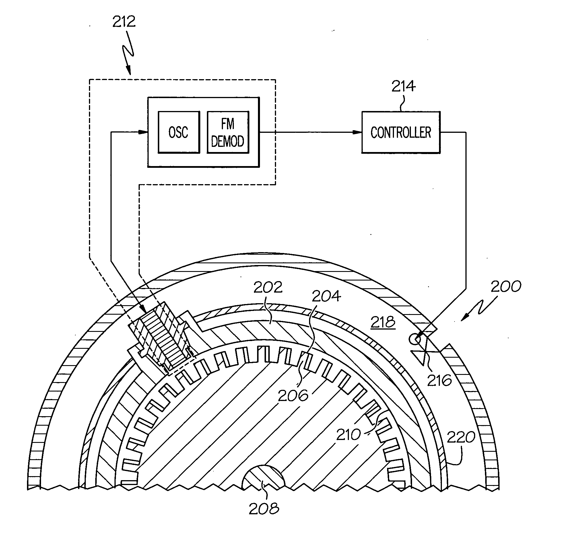
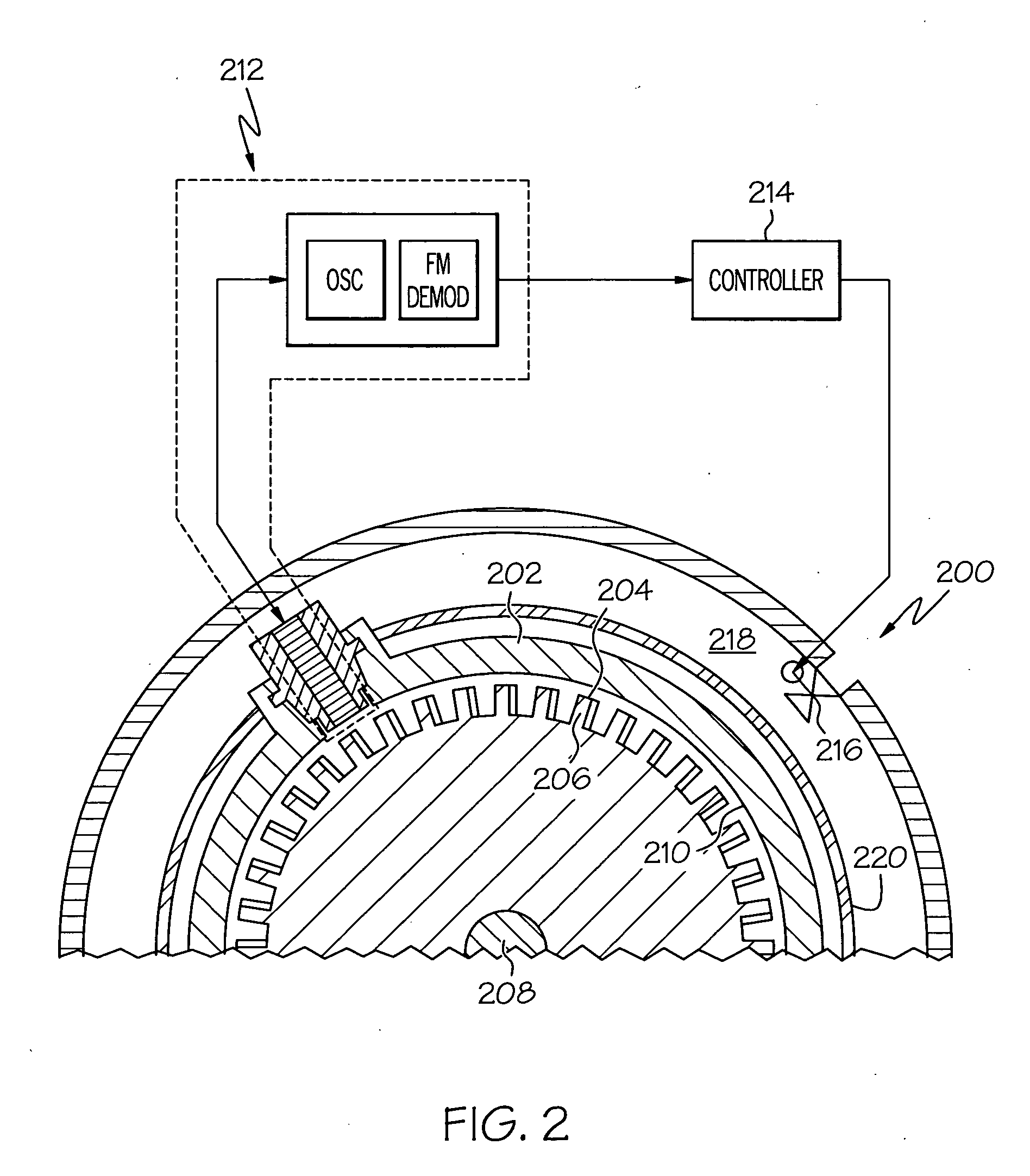
[0012] The present invention provides a turbine blade proximity sensor that exhibits sufficiently high and sufficiently consistent response, accuracy, and reliability in the potentially harsh gas turbine engine environment, and a control system that uses the proximity sensor to control the clearance between the turbine blades and one or more non-rotating turbine components.

Problems solved by technology

Additionally, the turbine's rotational speed increases, subjecting the blades to centrifugal forces that may cause radial blade growth.
However, the equilibrium temperature reached in various components of the turbines may result in the radial clearance between the turbine blades and annular seal being larger than desirable, resulting in undesirable leakage and concomitantly low engine efficiency.
Although safe and generally effective, presently known sensing and control systems suffer certain drawbacks.
Namely, the response characteristics, accuracy, and / or reliability of many of the above-mentioned proximity sensor types is not as high as desirable when use in the operating environment of a gas turbine engine.
As a result, proximity sensor replacement may be needed more often than is desirable, and turbine efficiency may be decreased, since proximity sensor accuracy may be low.
Both of these drawbacks can lead to increased system and operational costs.

Method used


Image

  • Turbine blade proximity sensor and control system
  • Turbine blade proximity sensor and control system
  • Turbine blade proximity sensor and control system

Examples


Embodiment Construction

[0024] Before proceeding with a detailed description, it is to be appreciated that the described embodiment is not limited to use in conjunction with a particular type of turbine engine, or even to use in a turbine. Thus, although the present embodiment is, for convenience of explanation, depicted and described as being implemented in a multi-spool turbofan gas turbine jet engine, it will be appreciated that it can be implemented in various other types of turbines, and in various other systems and environments.

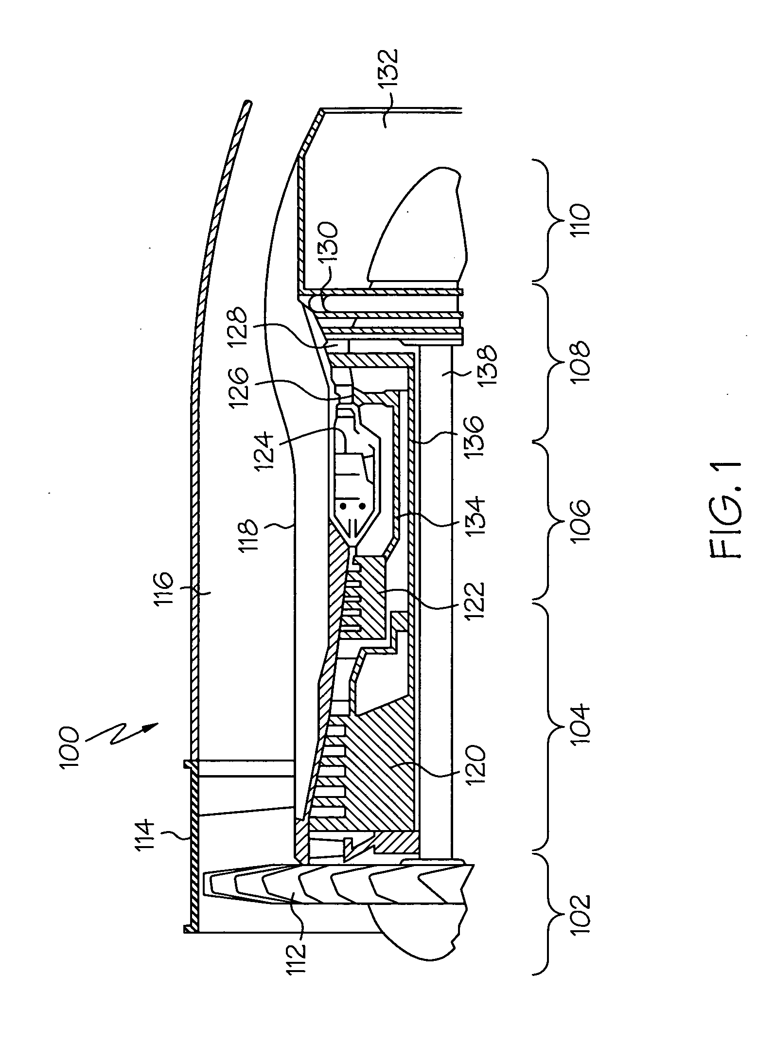
[0025] An exemplary embodiment of a multi-spool turbofan gas turbine jet engine 100 is depicted in FIG. 1, and includes an intake section 102, a compressor section 104, a combustion section 106, a turbine section 108, and an exhaust section 110. The intake section 102 includes a fan 112, which is mounted in a fan case 114. The fan 112 draws air into the intake section 102 and accelerates it. A fraction of the accelerated air exhausted from the fan 112 is directed through a by...


PUM


Abstract

A proximity sensor system uses a sensor coil as the frequency determining element of an oscillator circuit. The frequency of the oscillator circuit is thus modulated based on the proximity of the sensor coil to a conductive element, thereby supplying a frequency modulated sensor signal. A frequency modulation (FM) detector circuit demodulates the sensor signal, and supplies a signal having an amplitude that varies with, and is representative of, the proximity of the sensor coil to the conductive element.

Description

FIELD OF THE INVENTION [0001] The present invention relates to proximity sensors and, more particularly, to a proximity sensor and control system that senses and controls the proximity of rotating turbine blades to one or more non-rotating components. BACKGROUND OF THE INVENTION [0002] A gas turbine engine may be used to power various types of vehicles and systems. A particular type of gas turbine engine that may be used to power aircraft is a turbofan gas turbine engine. A turbofan gas turbine engine may include, for example, five major sections, a fan section, a compressor section, a combustor section, a turbine section, and an exhaust section. The fan section is positioned at the front, or “inlet” section of the engine, and includes a fan that induces air from the surrounding environment into the engine, and accelerates a fraction of this air toward the compressor section. The remaining fraction of air induced into the fan section is accelerated into and through a bypass plenum, ...

Claims


Application Information

Patent Timeline
IPC IPC(8): F01D17/02G01B7/14
CPCG01B7/14F01D17/02
Inventor GUALTIERI, DEVLIN M.
Owner HONEYWELL INT INC
Learn More