
High-frequency transmitting/receiving apparatus, radar system having the same, and vehicle and small boat equipped with the radar system

a high-frequency transmitting/receiving apparatus and radar technology, applied in the direction of instruments, waveguides, measurement devices, etc., can solve the problems of reducing the reception capability, affecting the operation of the vehicle, so as to reduce the influence of switching noise occurring in the switching device and simple configuration

Inactive Publication Date: 2005-04-28
KYOCERA CORP
View PDF4 Cites 42 Cited by
  • Summary
  • Abstract
  • Description
  • Claims
  • Application Information

AI Technical Summary

Benefits of technology

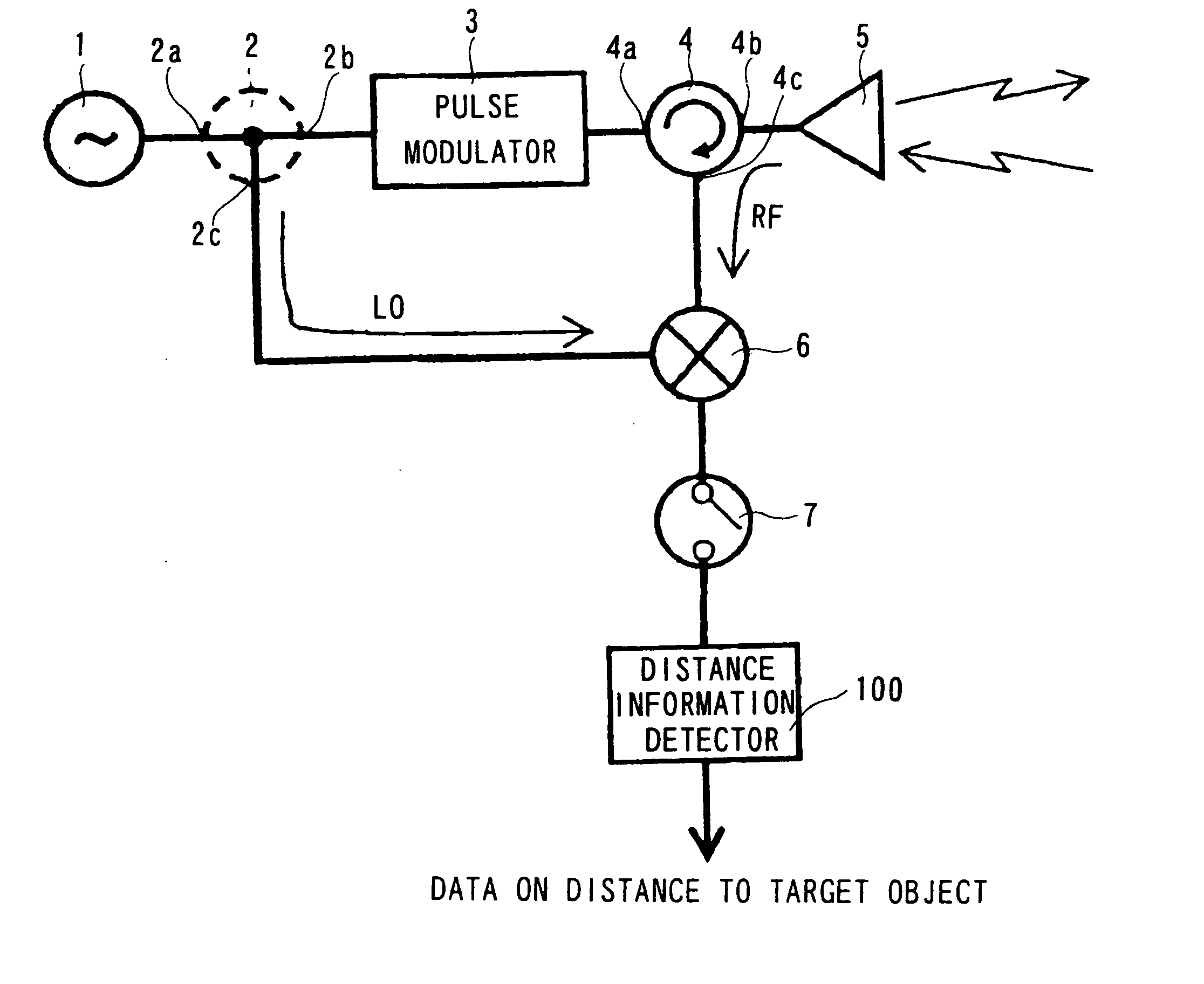
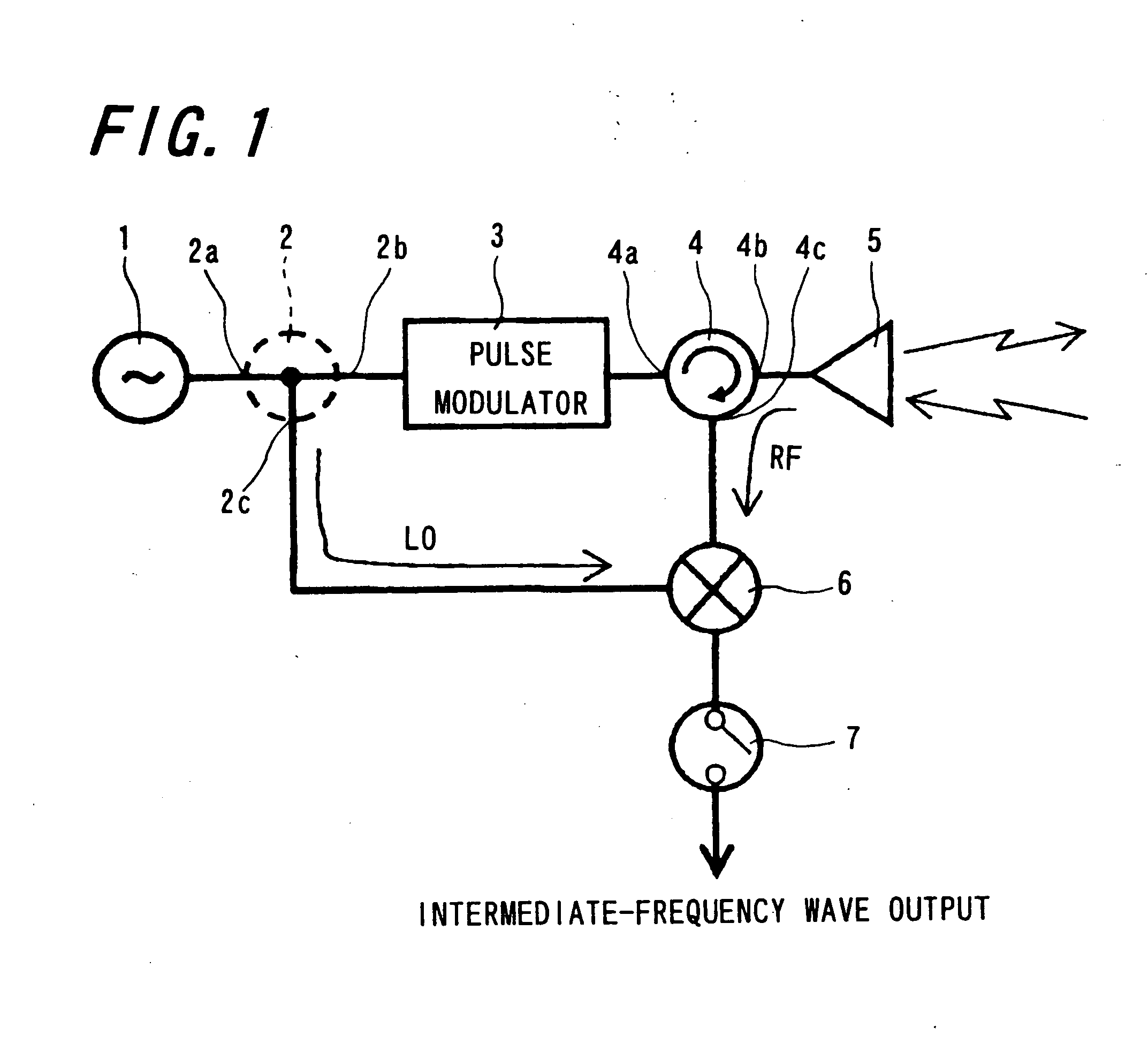
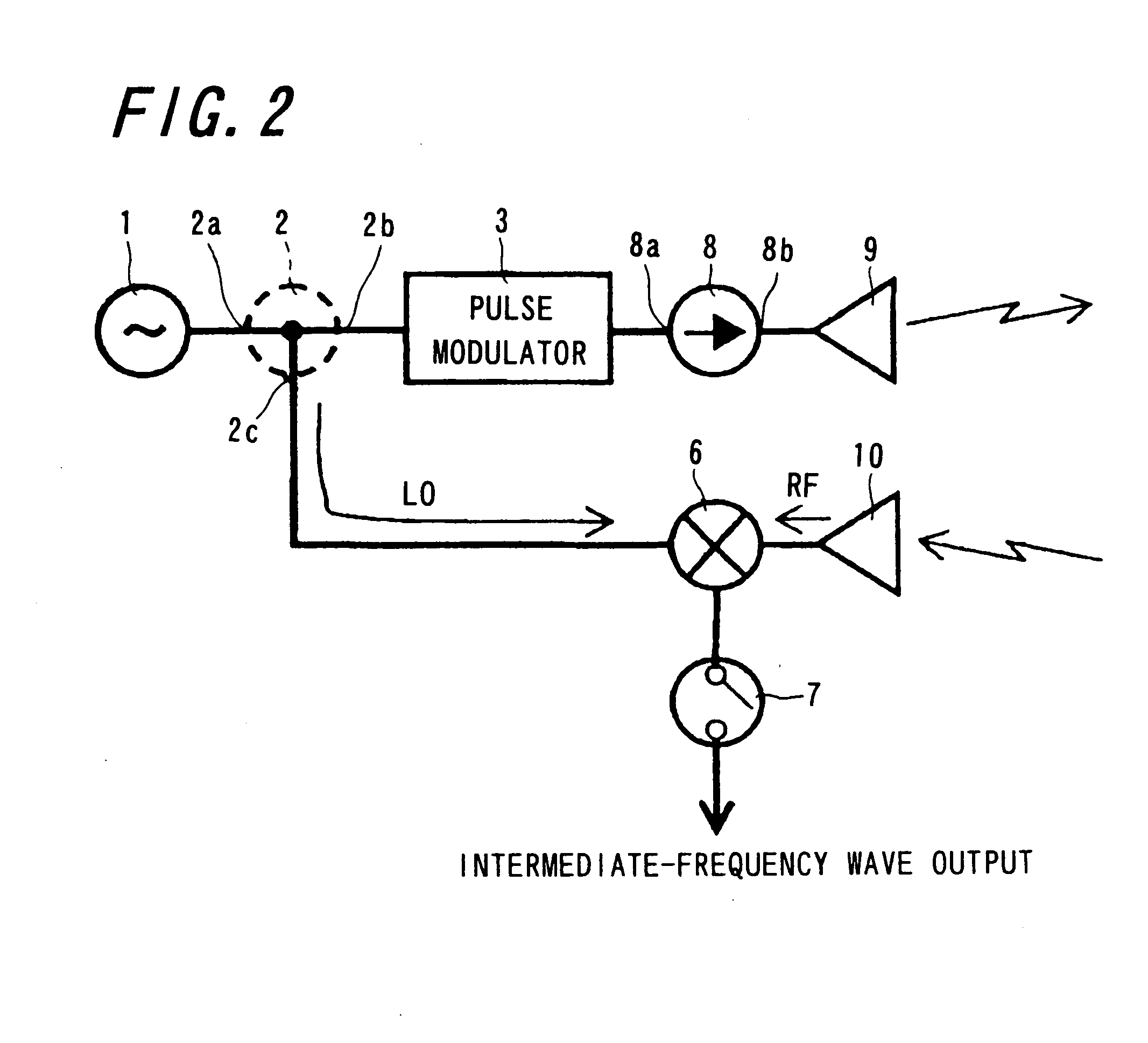
The invention provides a high-frequency transmitting / receiving apparatus with a switching device for avoiding pulse-modulated millimeter-wave signals from being outputted to a reception system due to inner reflection or other causes. The apparatus also includes a self-monitoring circuit to reduce the impact of switching noise. Additionally, the apparatus can monitor the operation of a transmission circuit by inputting a DC voltage source signal through a switching operation test. The invention also provides a high-performance radar system, a vehicle equipped with the radar system, and a small boat equipped with the radar system. The invention aims to enhance the reception performance of the high-frequency transmitting / receiving apparatus and improve the detection accuracy of the millimeter-wave radar system.

Problems solved by technology

However, in the pulse modulation method, part of a pulse-modulated millimeter-wave signal for transmission is outputted to a reception system, as an unwanted signal, due to reflection or other phenomena occurring within the high-frequency transmitting / receiving apparatus.
This gives rise to a problem of the reception capability being degraded.
Therefore, even if a pulse signal ideal for driving is inputted, a distortion such as ringing noise may appear in modulation current to a greater or lesser degree.
Furthermore, the pulse signal for driving itself may suffer from a similar distortion in varying degrees.
This leads to degradation in the radar detection performance.
At this time, if the switching timing signal is generated by using only the signal at the IN-1 terminal, there is a possibility that the ON-OFF timing cannot be controlled with high accuracy, or that the circuit for generating the timing signal is undesirably complicated.
Such a signal cannot be generated without using a time-delay circuit or the like.
However, the millimeter radar shown in FIG. 19 poses the following problems.
This requires much delay time in the CR delay circuit, with the result that the timing may be greatly varied even if variation in the circuit constant is slight.
Furthermore, with the addition of the CR delay circuit, the entire circuit configuration is undesirably complicated.
One of the problems is that switching noise is produced in accompaniment with switching of the switch 116.
However, because of its property, the switch 116 incurs switching noise, though slight, during switching operations.
As a result, the mixer 115 is brought into malfunction, and besides, a part of a multiple-reflected central frequency signal may find its way into the circuits located downstream of the switch 116, which ends in failure of proper outputting of intermediate-frequency signals.
If the reception inhibition timing is not controlled with high accuracy, the following problem arises.
If the reception operation is suspended at this time, there is a possibility that important information to be received is missed.

Method used


Image

  • High-frequency transmitting/receiving apparatus, radar system having the same, and vehicle and small boat equipped with the radar system
  • High-frequency transmitting/receiving apparatus, radar system having the same, and vehicle and small boat equipped with the radar system
  • High-frequency transmitting/receiving apparatus, radar system having the same, and vehicle and small boat equipped with the radar system

Examples


working example

[0408] As an working example, a millimeter-wave radar was constructed that has such a circuit configuration as shown in FIG. 10A. The NRD guide, which is a principal component constituting the millimeter-wave signal transmitting section of the millimeter-wave radar, is fabricated as follows. As shown in FIG. 18, as a pair of parallel plate conductors 41 and 42, two pieces of 6 mm-thick Al plates are disposed at an interval a of 1.8 mm. Between the Al plates is interposed a dielectric line 43 made of cordierite ceramics having a relative dielectric constant of 4.8. The dielectric line 43 has a sectional profile of 1.8 mm in height and 0.8 mm in width. Moreover, the millimeter-wave circuit constituting the millimeter-wave signal transmitting section is configured as shown in FIG. 16.

[0409] The capacitor 35 employed in the millimeter-wave radar is designed as follows. The correction capacitance value C0 of the capacitor 35 connected in parallel with the signal selector switch 34 is de...


PUM


Abstract

Provided is a millimeter-wave transmitting / receiving apparatus of pulse-modulation type in which pulse-modulated millimeter-wave signals for transmission are prevented from being outputted to a reception system due to inner reflection or other causes. Included are: an NRD guide (basic structure) formed of a dielectric line sandwiched between parallel plate conductors; a millimeter-wave signal oscillator; a pulse modulator; a circulator; a transmitting / receiving antenna; and a mixer. At the output end of the mixer is disposed a switching device which interrupts intermediate-frequency signals in an opened state, and, when a millimeter-wave signal for transmission from the pulse modulator enters a non-output state and the condition is stabilized, changes into a closed state to pass intermediate-frequency signals. The intermediate-frequency signal containing noise resulting from the millimeter-wave signal for transmission entering the mixer can be prevented from leaking toward downstream side of the mixer; wherefore a desired intermediate-frequency signal can be outputted.

Description

BACKGROUND OF THE INVENTION [0001] 1. Field of the Invention [0002] The present invention relates to a high-frequency transmitting / receiving apparatus employing a nonradiative dielectric waveguide (an NRD guide) for use in a millimeter-wave radar module, a millimeter-wave wireless radio communication apparatus, or the like, and more particularly to a high-frequency transmitting / receiving apparatus having a switching device for avoiding that a pulse-modulated millimeter-wave signal for transmission is outputted to a reception system due to inner reflection or other causes, wherein the influence of switching noise occurring in the switching device can be reduced. The invention also relates to a radar system having the high-frequency transmitting / receiving apparatus, a vehicle equipped with the radar system, and a small boat equipped with the radar system. [0003] 2. Description of the Related Art [0004] Conventionally, some types of high-frequency transmitting / receiving apparatuses hav...

Claims


Application Information

Patent Timeline
Patent Type & Authority Applications(United States)
IPC IPC(8): H01P3/16G01S7/03G01S13/937H04B1/54
CPCG01S13/9307G01S7/038G01S13/937
Inventor SAKAMOTO, YOSHIHIROKISHIDA, YUJIHAYATA, KAZUKIOYA, YOSHIKO
Owner KYOCERA CORP
Learn More