Optical transceiver module

Inactive Publication Date: 2005-04-28
IND TECH RES INST
View PDF23 Cites 26 Cited by
  • Summary
  • Abstract
  • Description
  • Claims
  • Application Information

AI Technical Summary

Benefits of technology

[0019] A casing of the multiplexer/demultiplexer is used as base of the optical transceiver module to accommodate the optical signal transmission/receiving units, the optical fibers and an upper lid, thereby enabling easy assembly of the module with a reduce

Problems solved by technology

However, since the optical receiver and the optical transmitter are integrated in a casing of the optical transceiver module, some problems may occur concerning heat dissipation, the arrangement of the optical fibers, and the alignment of the pins of the circuit board with through holes of substrates of other electronic devices, electromagnetic interference and electromagnetic radiation.
Therefore, heat dissipation efficiency is not satisfactory.
Although a commercially available optical fiber connector can be adapted to connect the optical fiber, the optical receiver 13 and the optical

Method used


Image

  • Optical transceiver module
  • Optical transceiver module
  • Optical transceiver module

Examples


Example

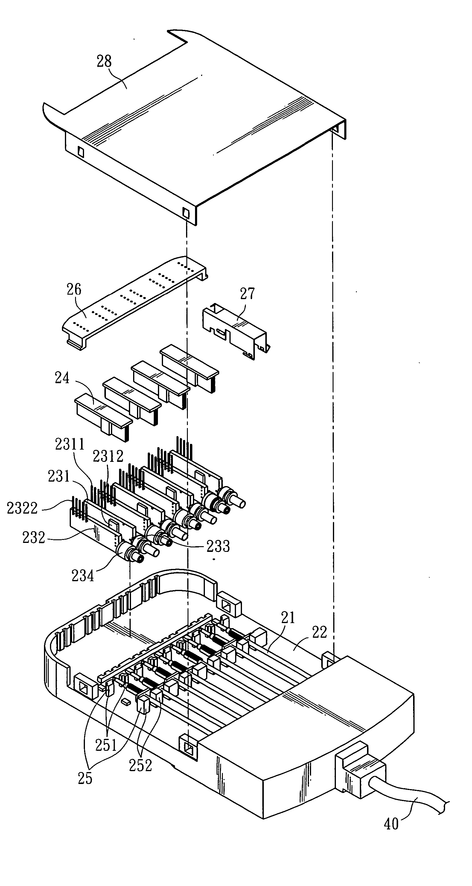
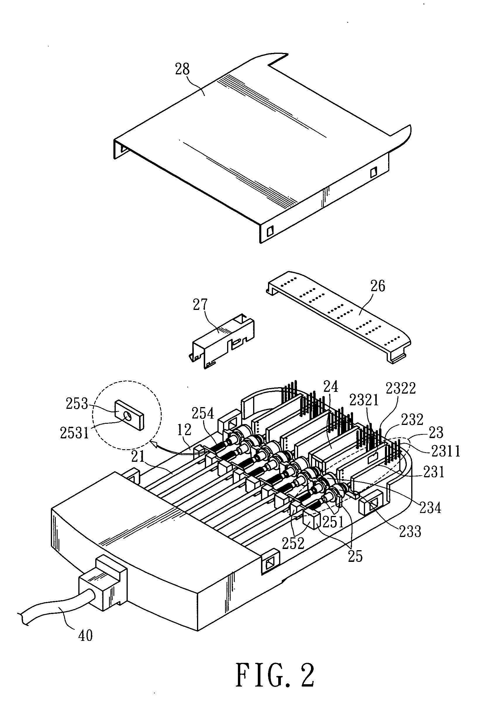
[0042]FIG. 2 is a perspective view of an optical transceiver module (shown without the assembly of a guiding plate 26 and an upper lid 28) according to one embodiment of the invention. FIG. 3 is an exploded view of an optical transceiver module according to one embodiment of the invention. The optical transceiver module is suitable for signal transmission in a metropolitan area network (MAN), and its features determine data transmission speed. As shown, the optical transceiver module receives and transmits optical signals from and to a communication device (not shown) via coupled optical fibers 21. Aside optical fiber media, signal transmission can be achieved via other media such as, free space or PLC. However, the embodiments of the invention will be exemplary illustrated with the utilization of optical fibers as communication means.

[0043] The optical transceiver module includes a base 22, an optical signal transmission / receiving unit 23, a heat sink 24, a fastening unit 25, a gu...


PUM


Abstract

An optical transceiver module includes a plurality of optical signal transmission/receiving units to receive and transmit optical signals, and is fastened to a base by a fastening unit. Each optical signal transmission/receiving unit includes a heat sink to promote heat dissipation efficiency. An electromagnetic shielding part covers the optical receiver to isolate from electromagnetic interference. A guiding plate is provided in the module to comb terminals of the module when the low-density wavelength-multiplex transceiver module is to be placed in an electronic device.

Description

BACKGROUND OF THE INVENTION [0001] 1. Field of Invention [0002] The present invention relates to an optical transceiver module, suitable for optical transmission through a small LAN. [0003] 2. Related Art [0004] The application of optical fiber communication has been extended from long-distance telecommunication network and cable TV network to short-distance LAN and client loop. Optical communication devices and their production are crucial to optical fiber communication technology. In the future, it can be expected that optical fiber communication networks will be popularized to domestic appliances. At that time, active devices and module technology will play a preponderant role in such an advance. [0005] An optical transceiver module is mounted in an electronic device for optical transmission via the optical fibers of an optical transceiver module. FIG. 1 is a perspective view of an optical transceiver module. The optical transceiver module includes a casing 11, a base 12, an opti...

Claims


Application Information

Patent Timeline
IPC IPC(8): G02B6/34G02B6/36G02B6/42
CPCG02B6/4201G02B6/4249G02B6/4246G02B6/4215G02B6/4245G02B6/4261G02B6/4269G02B6/4277G02B6/428
Inventor CHIU, CHIA-HUNGSHAW, CHENG-DACHEN, YI-MINGWANG, CHIUNG-HUNGCHANG, YUAN-JENHSU, CHI-LUNHUANG, MING-FAHSU, CHIH-HAO
Owner IND TECH RES INST
Why Eureka
Try Eureka