Method for fomring a self-aligned ltps TFT

a thin film transistor and self-aligning technology, applied in the direction of transistors, electrical devices, semiconductor devices, etc., can solve the problems of high quality and low price of flat panels, misalignment or overlap, etc., and achieve the effect of increasing superfluous processes and excessive costs

Inactive Publication Date: 2005-04-28
AU OPTRONICS CORP
View PDF5 Cites 17 Cited by
  • Summary
  • Abstract
  • Description
  • Claims
  • Application Information

AI Technical Summary

Benefits of technology

[0014] It is therefore one object of the present invention to provide a method for forming an LTPS TFT that can self align the lightly doped drains, the source electrode, and the drain electrode, such that the error resulting from the photo process can be avoided.
[0015] It is another object of the present invention to provide a method for forming an LTPS CMOS TFT in a self-aligned manner to obtain symmetric lightly doped drains without superfluous processes.
[0017] The present invention first utilizes the patterned conductive layer as a self-aligned mask to form the N type source and the N type drain, then utilizes the reduced patterned conductive layer as a self-aligned mask to form the N type lightly doped drain and the gate electrode, and finally utilizes the gate electrode as a self-aligned mask to form the P type source and the P type drain. The present invention utilizes multiple self-aligned processes to form the LTPS TFT, which does not increases superfluous processes and excessive costs, but obtains symmetric N type lightly doped drains. Furthermore, the misalignment problem due to multiple photo-etching processes can be avoided.

Problems solved by technology

As the requirements of high quality displays increase, flat panels with high quality and low price are demanding in the future.
However, when defining the pattern of the photo resist mask in a photo process by a stepper or a scanner, misalignment or overlap could occur because of human or non-human factors.
The asymmetric lightly doped areas 20 not only are incapable of restraining the hot electron effect, but may also generate leakage current of the gate electrode, and further result in breakdown.

Method used


Image

  • Method for fomring a self-aligned ltps TFT
  • Method for fomring a self-aligned ltps TFT
  • Method for fomring a self-aligned ltps TFT

Examples


Embodiment Construction

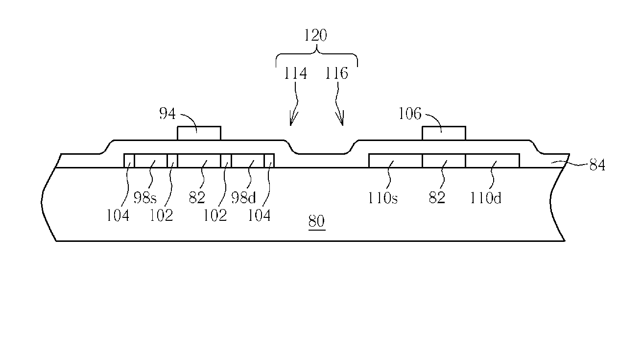
[0022] The present invention provides a method for simultaneously forming an NLTPS TFT and a PLTPS TFT. However, the application of the present invention is not limited by the embodiments. In a preferred embodiment of the present invention, the method of the present invention can be also applied to form an LTPS CMOS TFT composed of an NLTPS TFT and a PLTPS TFT. The LTPS CMOS TFT, NLTPS TFT, or PLTPS TFT of the present invention is formed in a periphery circuit area of an LCD for being a logic device. Moreover, the NLTPS TFT used to be a switching device could also be formed by the method of the present invention in a pixel array area of the LCD.

[0023] An example of forming an LTPS CMOS TFT 74 is used here for illustrating the method of the present invention. FIGS. 6-14 are schematic diagrams of a method for forming the LTPS CMOS TFT 74 according to a preferred embodiment of the present invention. As shown in FIG. 6, the LTPS CMOS TFT 74 is formed on a substrate 40, and the substrat...


PUM


Abstract

A method for forming a self-aligned low temperature polysilicon thin film transistor (LTPS TFT). First, active layers of a N type LTPS TFT (NLTPS TFT) and a P type LTPS TFT (PLTPS TFT) are formed on a substrate, and a gate insulating (GI) layer is formed on the substrate. Then, a source electrode, a drain electrode, and lightly doped drains (LDD) of the NLTPS TFT are formed. Further, gate electrodes of the NLTPS TFT and the PLTPS TFT are formed on the gate insulating layer. Finally, the gate electrode of the PLTPS TFT is utilized to form a source electrode and a drain electrode in the active layer of the PLTPS TFT.

Description

CROSS REFERENCE TO RELATED APPLICATIONS [0001] This application is a division of application Ser. No. 10 / 604,225 filed on Jul. 2, 2003BACKGROUND OF THE INVENTION [0002] 1. Field of the Invention [0003] The present invention relates to a method for forming a low temperature polysilicon thin film transistor (LTPS TFT), and more particularly, to a method for forming a self-aligned LTPS TFT. [0004] 2. Description of the Prior Art [0005] A liquid crystal display is broadly applied to portable electronic apparatuses, such as notebooks and personal digital assistants (PDAs), because of its thin display panel, low power consumption, and low-radiation. As the requirements of high quality displays increase, flat panels with high quality and low price are demanding in the future. An LTPS TFT, which is an actively driving TFT, is one of the important technologies for achieving the goal. [0006] An LTPS TFT-LCD includes at least a transparent substrate, a pixel array region, a scan line driving c...

Claims


Application Information

Patent Timeline
Patent Type & Authority Applications(United States)
IPC IPC(8): H01L21/336H01L21/77H01L21/84H01L27/12H01L29/786
CPCH01L27/1214H01L29/78618H01L29/66757H01L27/127H01L27/1288H01L27/1274
Inventor CHANG, CHIH-CHIN
Owner AU OPTRONICS CORP
Why Eureka
Try Eureka