Comprehensive tissue attachment system

Inactive Publication Date: 2005-04-28
GEDEBOU TEWODROS
View PDF27 Cites 470 Cited by
  • Summary
  • Abstract
  • Description
  • Claims
  • Application Information

AI Technical Summary

Benefits of technology

[0019] It is therefore an object of the present invention to provide a bone anchor operative to provide an optimal degree of tension or support to a suture affixed thereto, and in particular, provide means for selectively adjusting the degree of tension and/or support imparted by the suture affixed thereto.
[0020] Another object of the present invention is to provide a bone anchor having means for selectively adjusting the degree of tension possessed by a suture and/or the degree of support imparted thereby that can be manipulated post-operatively without requiring a further surgical procedure.
[0021] Another object of the present invention is to provide a system and method for attaching ligaments/tendons directly to bone to thus define a soft tissue/bone connection or interface that further can enable such conjoined structures to be selectively positioned or interconnected at a precise level of tension.
[0022] Another object of the present invention is to provide a bone anchor having means to selectively adjust the degree of tension of a suture affixed thereto or the degree of support imparted by a suture hel

Problems solved by technology

Although such prior art bone anchor devices generally provide sufficient support to the various sutures and structures affixed thereto, such fixation devices suffer from several well-known draw backs.
Perhaps most problematic with such devices is the inability to make any kind of adjustment once a suture is affixed thereto.
Such limitation further complicates post-operative procedures to the extent a given suture is sub-optimally affixed to a given anchor.
In this regard, it is well-known that following a given surgical procedure where a bone anchor is implemented to suspend or support a given suture, such attachment may unfortunately impart too much or too little tension or support.
As is well-known, to undergo yet a further surgical procedure causes substantial discomfort to the patient, substantially increases health care costs, and wastes health care resources.
Separate and apart from the aforementioned drawba

Method used


Image

  • Comprehensive tissue attachment system
  • Comprehensive tissue attachment system
  • Comprehensive tissue attachment system

Examples


first embodiment

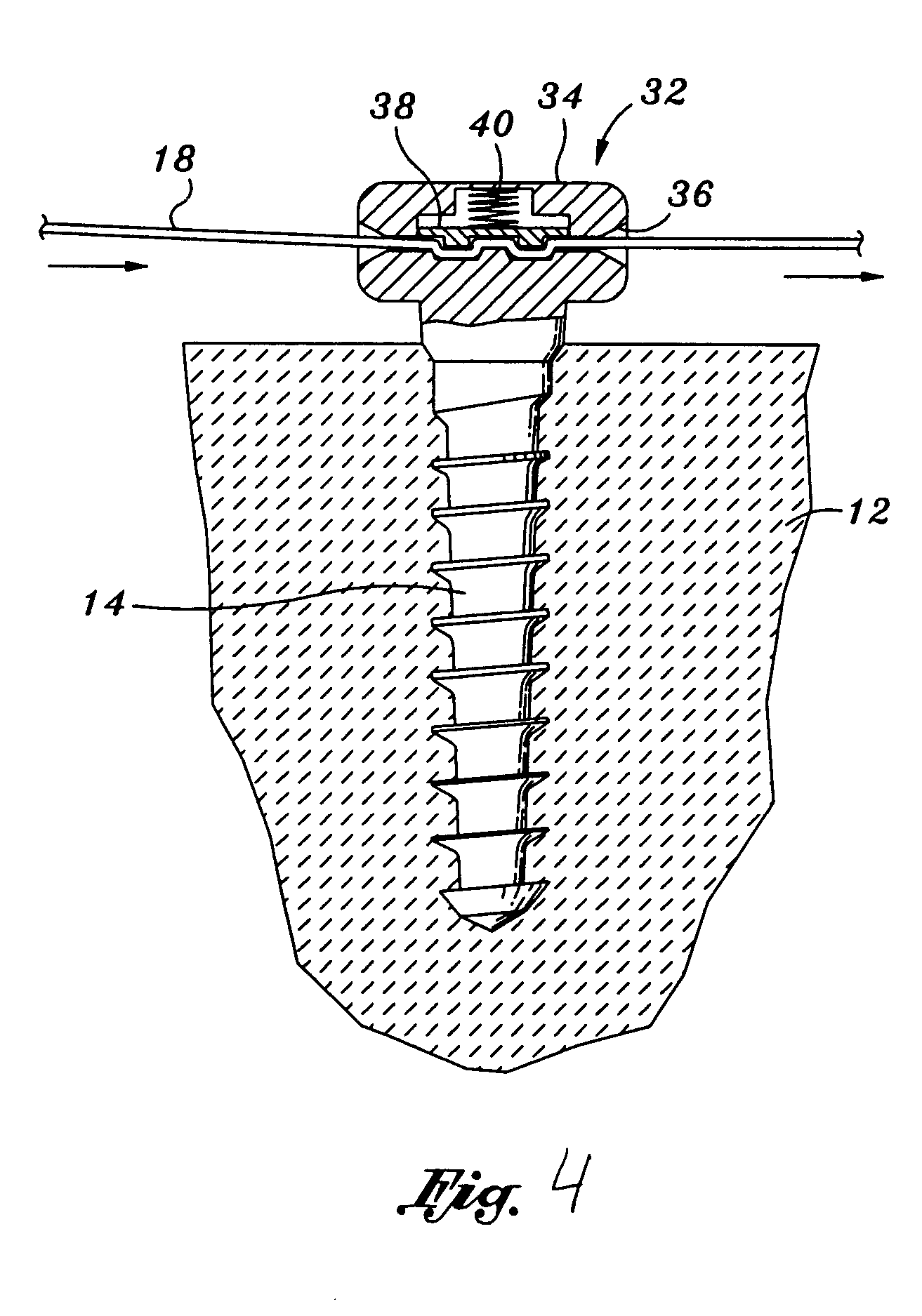
[0059] In further refinements of the embodiment depicted in FIG. 4, it is contemplated that the same may be adapted for non-surgical, post-operative manipulation to thus enable the tension held by suture 18 to be selectively modified without having the patient to undergo further surgical procedures. To that end, it is contemplated that a magnetic element, which may be embedded within or encompass all of brake member 38, may be formed of a magnetic material such that application of a magnetic field is operative to cause brake member 38 to compress upwardly against spring 40, which in turn releases the suture 18 from its seated position within housing 34 and operative to adjust the tension held by such suture. As per the first embodiment, however, it is contemplated that a variety of alternative tension adjusting mechanisms will be readily-appreciated by those skilled in the art and that the scope of the present invention is deemed to encompass all such embodiments.

embodiment 42

[0060] Referring now to FIGS. 5-7, there is shown a further embodiment 42 of a bone anchor constructed in accordance with the preferred embodiment of the present invention. Unlike the previous embodiments, the embodiment depicted is operative to define a channel extending completely through a section of bone through which sutures may be positioned and operatively adjusted to provide a desired degree of tension or support as depicted in FIG. 7. Such embodiment consists of a body portion or housing 44, which preferably has a generally frusto-conical shape operative to nest within a generally conically shaped bore made through bone 12. Disposed within such housing 44 is a channel 56 defining a passageway through which a suture 18 can extend. As will be appreciated by those skilled in the art, although depicted having a generally frusto-conical configuration, it will be recognized that such housing 44 may take any of a variety of well-known shapes and forms that are operative to define ...

embodiment 60

[0064] Referring now to FIGS. 8-10, there is shown yet another embodiment 60 of a bone anchor operative to secure and selectively control the degree of tension held within a suture line. Such embodiment 60 is comprised by the combination of a housing portion 62 depicted in FIG. 8, and a tension adjustment mechanism 64, depicted in FIG. 9. With respect to the former, the same includes a housing portion 65 defining an upper portion 66 through which the tension of the suture is selectively adjusted, and a distal portion 68 operative to define a channel through which the sutures are received through a bore made through bone 12. In this regard, such housing 62 will define a passageway 70 through which a suture 90 may extend, as depicted in FIG. 10.

[0065] The tension adjustment mechanism 64 depicted in FIG. 9, similar to the embodiment depicted in FIGS. 2 and 3, essentially relies on a ratchet-type system. As illustrated, such tension adjustment mechanism is provided with an elongate post...


PUM


Abstract

Bone anchors, methods for deploying anchors, and systems for attaching ligaments and tendons to bone are disclosed. The bone anchors of the present invention are operative to remain firmly positioned within a target site of bone and provide means for selectively adjusting the degree of tension to one or more sutures secured thereto. The bone anchors are further operative to be utilized to connect tendons and ligaments directly to bone, as well as may be selectively utilized to adjustably position an implant or other anatomical structure held thereby. There is further disclosed methods for deploying a bone anchor utilizing a blind procedure that is expeditious, accurate and substantially less traumatic than prior art bone deployment techniques.

Description

CROSS-REFERENCE TO RELATED APPLICATIONS [0001] Not Applicable STATEMENT RE: FEDERALLY SPONSORED RESEARCH / DEVELOPMENT [0002] Not Applicable BACKGROUND OF THE INVENTION [0003] Surgical procedures requiring the attachment of anatomical structures, such as implants, sutures, grafts, slings, and the like to various points within the body are well-known. Typically, such anatomical structures are secured into position via a variety of anchoring mechanisms, known as surgical suture anchors or bone anchors, that typically provide a secure point of attachment to which an anatomical structure can be attached or otherwise supported. In this respect, such anchors are operative to attach a variety of anatomical structures and the like to bone and have found widespread applicability for a number of surgical procedures. In particular, bone anchors are extensively utilized in orthopedic and gynecologic procedures, as well as plastic and reconstructive surgery, where the same can be utilized to selec...

Claims


Application Information

Patent Timeline
IPC IPC(8): A61B17/04A61B17/58
CPCA61B17/0401A61B2017/0409A61B2017/0496A61B2017/044A61B2017/0414A61F2/0811A61F2002/0829A61F2002/0864A61F2002/0882
Inventor GEDEBOU, TEWODROS
Owner GEDEBOU TEWODROS
Why Eureka
Try Eureka