Incorporation of a phase map into fast model-based optical proximity correction simulation kernels to account for near and mid-range flare

a phase map and simulation kernel technology, applied in the field of optical microlithography, can solve the problems of low simulation efficiency, hampered data analysis, and low simulation efficiency of simulation kernels, and achieve the effect of fast model-based simulation kernels and simulation kernels

a phase map and simulation kernel technology, applied in the field of optical microlithography, can solve the problems of low simulation efficiency, hampered data analysis, and low simulation efficiency of simulation kernels, and achieve the effect of fast model-based simulation kernels and simulation kernels

US20050091013A1Inactive Publication Date: 2005-04-28GLOBALFOUNDRIES INC

Image

  • Incorporation of a phase map into fast model-based optical proximity correction simulation kernels to account for near and mid-range flare
  • Incorporation of a phase map into fast model-based optical proximity correction simulation kernels to account for near and mid-range flare
  • Incorporation of a phase map into fast model-based optical proximity correction simulation kernels to account for near and mid-range flare

Examples


Embodiment Construction

)

[0045] In describing the preferred embodiment of the present invention, reference will be made herein to FIGS. 11-11 of the drawings in which like numerals refer to like features of the invention.

[0046] The present invention provides a method to compute a phase map that can be used to take into account the higher order aberrations within an optical proximity correction simulation kernel, which results in a more accurate computation of OPC when long-range effects become prominent.

[0047] Inverse Fourier transforms are used to create a phase map that accounts for higher order aberrations normally ignored in traditional optical proximity correction (OPC) simulation kernels. Two methodologies are proposed to account for the higher order aberrations. The first method utilizes simulated wavefront information from randomly generated data. The second method uses measured or empirically derived data from optical tools.

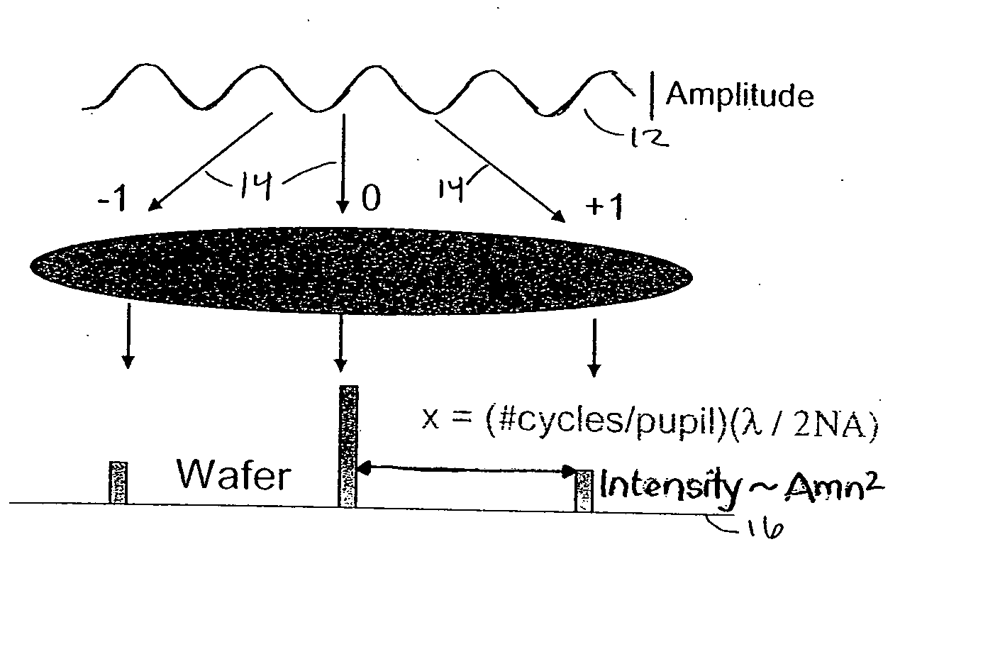
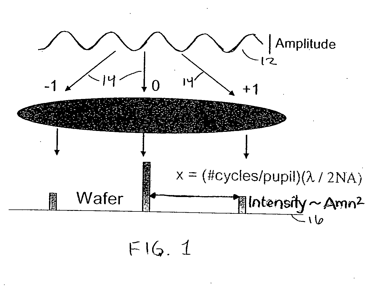
[0048] In both methods, flare is accounted for. FIG. 1 depicts a wavefr...


PUM


Abstract

A first method to compute a phase map within an optical proximity correction simulation kernel utilizes simulated wavefront information from randomly generated data. A second method uses measured data from optical tools. A phase map is created by analytically embedding a randomly generated two-dimensional array of complex numbers of wavefront information, and performing an inverse Fourier Transform on the resultant array. A filtering function requires the amplitude of each element of the array to be multiplied by a Gaussian function. A power law is then applied to the array. The elements of the array are shuffled, and converted from the phasor form to real / imaginary form. A two-dimensional Fast Fourier Transform is applied. The array is then unshuffled, and converted back to phasor form.

Description

CROSS-REFERENCE TO RELATED APPLICATIONS [0001] The present application is related to commonly assigned U.S. patent application Ser. No. ______ (Attorney Docket No. FIS920030107, titled “EXTENDING THE RANGE OF LITHOGRAPHIC SIMULATION INTEGRALS TO INCLUDE INTERMEDIATE DISTANCE SCALES”), U.S. patent application Ser. No. ______ (Attorney Docket No. FIS920030109, titled “IMPROVEMENT OF PERFORMANCE IN SECTOR-BASED OPC ENGINE UTILIZING EFFICIENT POLYGON PINNING METHOD AND SIMULTANEOUS COMPUTATION OF MULTIPLE SAMPLE POINTS”), U.S. patent application Ser. No. ______ (Attorney Docket No. FIS920030110, titled “RENESTING FLAREMAP INTO DESIGN FOR EFFICIENT LONG-RANGE FLARE CALCULATION”), and U.S. patent application Ser. No. ______ (Attorney Docket No. FIS920030262, titled “PARALLEL COMPUTATION OF MULTIPLE POINTS ON ONE OR MULTIPLE CUT LINES”), filed on even date herewith, which are hereby incorporated by reference herein in their entirety.BACKGROUND OF THE INVENTION [0002] 1. Field of the Invent...

Claims


Application Information

Patent Timeline
28 Apr 2005
Publication
US20050091013A1
IPC
G03F1/08; G03F1/14; G03F7/20; G06F17/10; H01L21/00; H01L21/027
CPC
G03F1/144; G03F7/705; G03F7/70441; G03F1/36; G03F1/70
Inventors
GALLATIN, GREGG M.; GOFMAN, EMANUEL