Hydraulic pressure sensor

a technology of hydraulic pressure sensor and sensor body, which is applied in the direction of fluid pressure measurement by electric/magnetic elements, measuring devices, instruments, etc., can solve the problems of reducing affecting the accuracy of hydraulic pressure measurement, so as to facilitate the adjustment of the desired frictional force and increase the frictional force

Inactive Publication Date: 2005-05-05
TIEFENBACH BERGBAUTECHN
View PDF5 Cites 15 Cited by
  • Summary
  • Abstract
  • Description
  • Claims
  • Application Information

AI Technical Summary

Benefits of technology

[0020] More particularly, the intermediate springs may be in the form of a rubber ring which is inserted into an annular groove in the opposing surface of one of the piston sections, and an annular bead that corresponds to the size of the groove is positioned on the opposing surface of the other piston section. This prevents the rubber rings from being damaged as a consequence of the occurring high compressive forces. In other words, the rubber rings are prevented from laterally yielding and from being squeezed under the great force of the pressure being measured.
[0021] As aforesaid, the partitions or piston sections of the partition extend along the inside wall of the reservoir housing in a sliding and sealing manner. A suitable seal is provided by a sealing ring arranged in a circumferential groove in the piston. This construction also facilitates the adjustment of the desired frictional forces.
[0022] The elastic rings in use for the seal may also have a double function, in that they serve for sealing and exerting sliding frictional forces on the one hand. On the other hand, they are used to support the piston sections. This will apply in particular when the rings have a rectangular or oval cross section, i.e., they are longer in the axial direction than in the radial direction. In this case, the high pressure that develops in the reservoir chamber or in the chamber sections will cause the rings to bulge outward, thereby increasing the frictional forces that are needed for the movement of the partition or piston sections.

Problems solved by technology

The disadvantage of this measure lies in that the hose connection is susceptible to damage, ageing, and leakage.
Furthermore in many cases, it also represents an obstacle.

Method used


Image

  • Hydraulic pressure sensor
  • Hydraulic pressure sensor
  • Hydraulic pressure sensor

Examples


Embodiment Construction

[0027] The following description and the applied numerals will apply to all embodiments, unless express reference is made to special features.

[0028] The invention is used for measuring the pressure of hydraulic fluids in hydraulic engines or machines. Preferably, the invention is applied to high pressures of more than 100 bars, since in this case pressure fluctuations have a high absolute value, and therefore tend to damage or misalign the sensor element in particular.

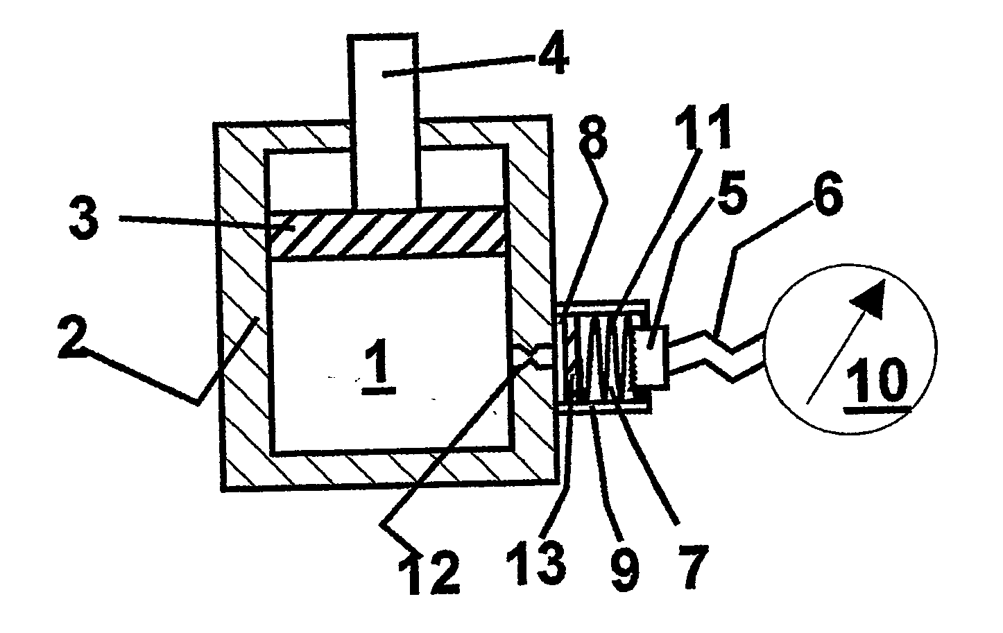
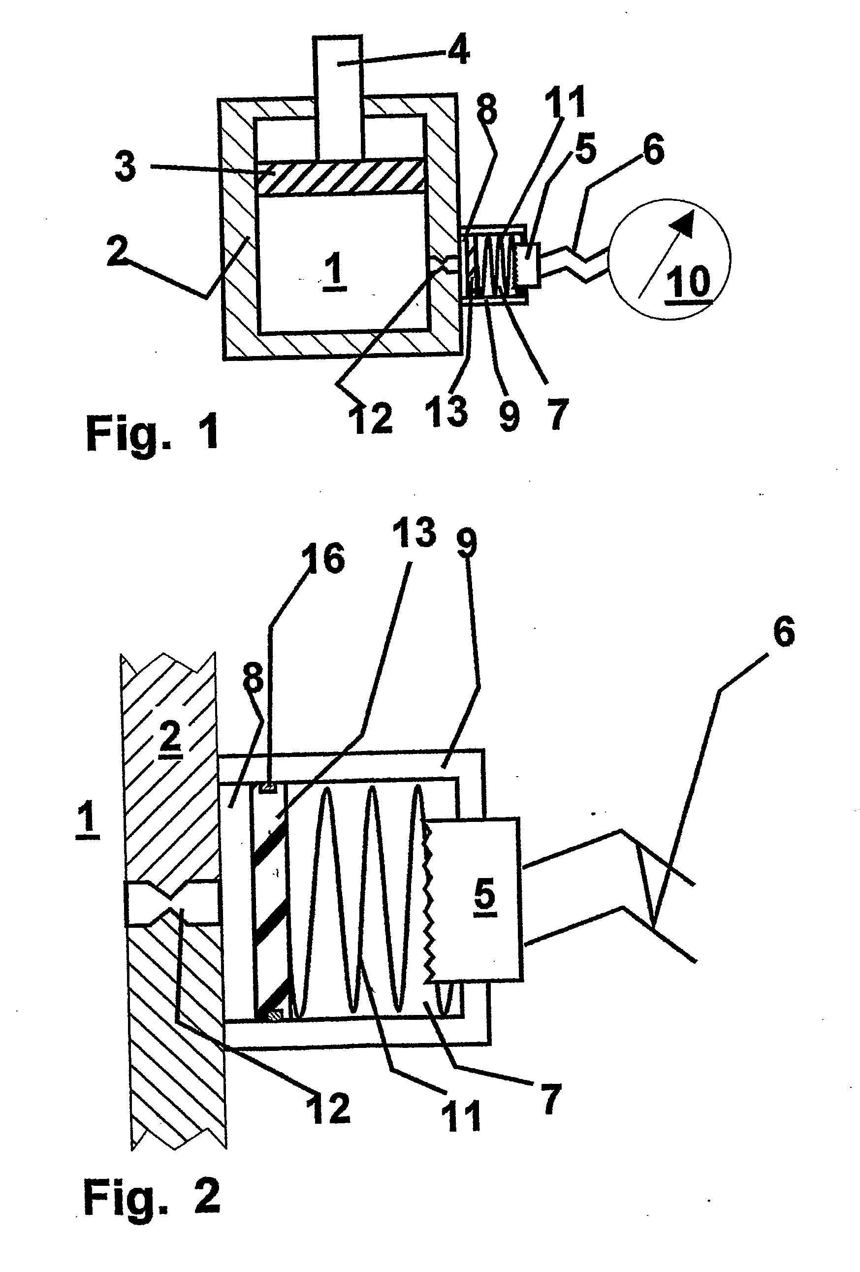
[0029]FIG. 1 schematically illustrates a hydraulic machine in the form of a cylinder 2 with a piston 3 and a plunger 4. Of this cylinder 2, the further embodiments show each only a wall 2 as well as a nozzle 12, which connects a pressure chamber 1 of the machine to a sensor chamber 7. To this end, a cylindrical equalization reservoir housing 9 is secured to the wall 2 of the cylinder and connects via a nozzle or flow control channel 12 to the pressure chamber 1. The reservoir housing 9 has a pressure resistant rigid ...


PUM

PropertyMeasurementUnit
pressuresaaaaaaaaaa
pressuresaaaaaaaaaa
pressureaaaaaaaaaa

Abstract

A hydraulic pressure sensor for measuring the pressure in a hydraulic pressure chamber 1. A reservoir housing 9 is connected to the pressure chamber, and the interior of the housing is divided by a slideable partition 13 which defines a reservoir chamber 8 which is connected to the pressure chamber and a sensor chamber 7 which is connected to a sensor element 5. The partition 13 is constructed as a piston and extends for sliding movement along the walls of the reservoir housing while exerting a frictional force. A spring 11 supports the partition relative to the reservoir housing against the pressure in the reservoir chamber 8. The partition 13 may be constructed as a differential piston, and consist of two or more piston sections 13.1, 13.2, 13.3, which extend independently of one another in a sliding and sealing manner, and mutually support one another by an intermediate spring 14.

Description

CROSS REFERENCE TO RELATED APPLICATION [0001] This is a continuation of international application PCT / DE 03 / 01652, filed May 21, 2003. The disclosure of said application is incorporated herein by reference.BACKGROUND OF THE INVENTION [0002] The present invention relates to a hydraulic pressure sensor for measuring the pressure in a hydraulic pressure chamber. [0003] When measuring the pressure, in particular in hydraulic consumers, for example, hydraulic working cylinders, there arises the problem that great pressure fluctuations may lead to damage or misalignment of the calibrated pressure sensor. This applies in particular to pressure sensors, namely in the case of sensor elements, which comprise a diaphragm that is deformable under the pressure of the sensor chamber, and to which electronic components are applied by gluing, vapor deposition or otherwise for representing an electric bridge. [0004] It is therefore common practice to accommodate such sensor elements in a sensor cham...

Claims


Application Information

Patent Timeline
Patent Type & Authority Applications(United States)
IPC IPC(8): G01L9/00G01L19/06
CPCG01L19/0609G01L9/0089
Inventor KUSSEL, WILLY
Owner TIEFENBACH BERGBAUTECHN
Why Eureka
Try Eureka