

Cooking appliance door with an inner borosilicate glass window pane and cooking appliance with said door
- Summary
- Abstract
- Description
- Claims
- Application Information
AI Technical Summary
Benefits of technology
Problems solved by technology
Method used
Image

Examples
Embodiment Construction
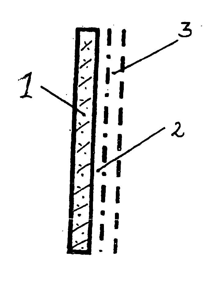
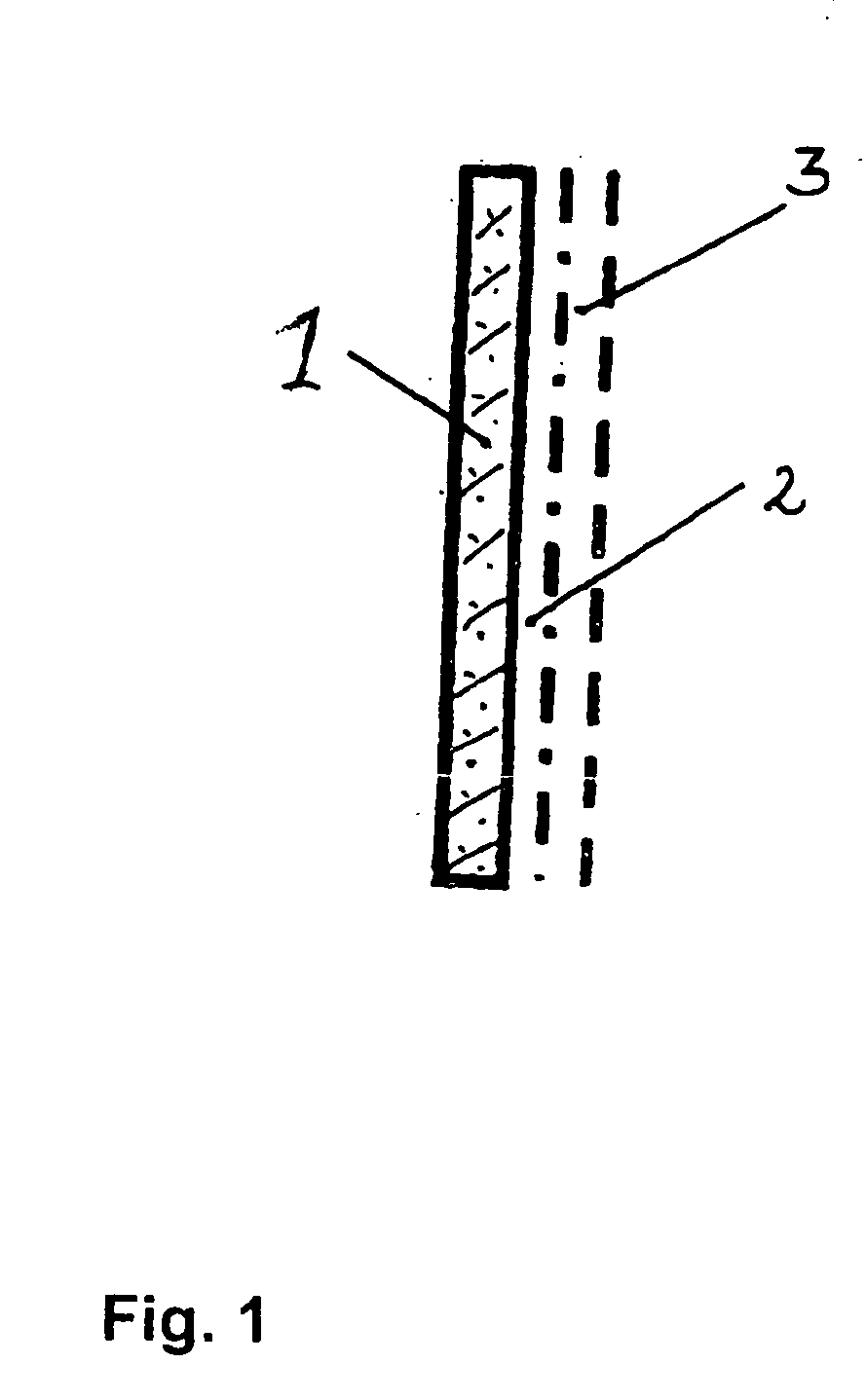
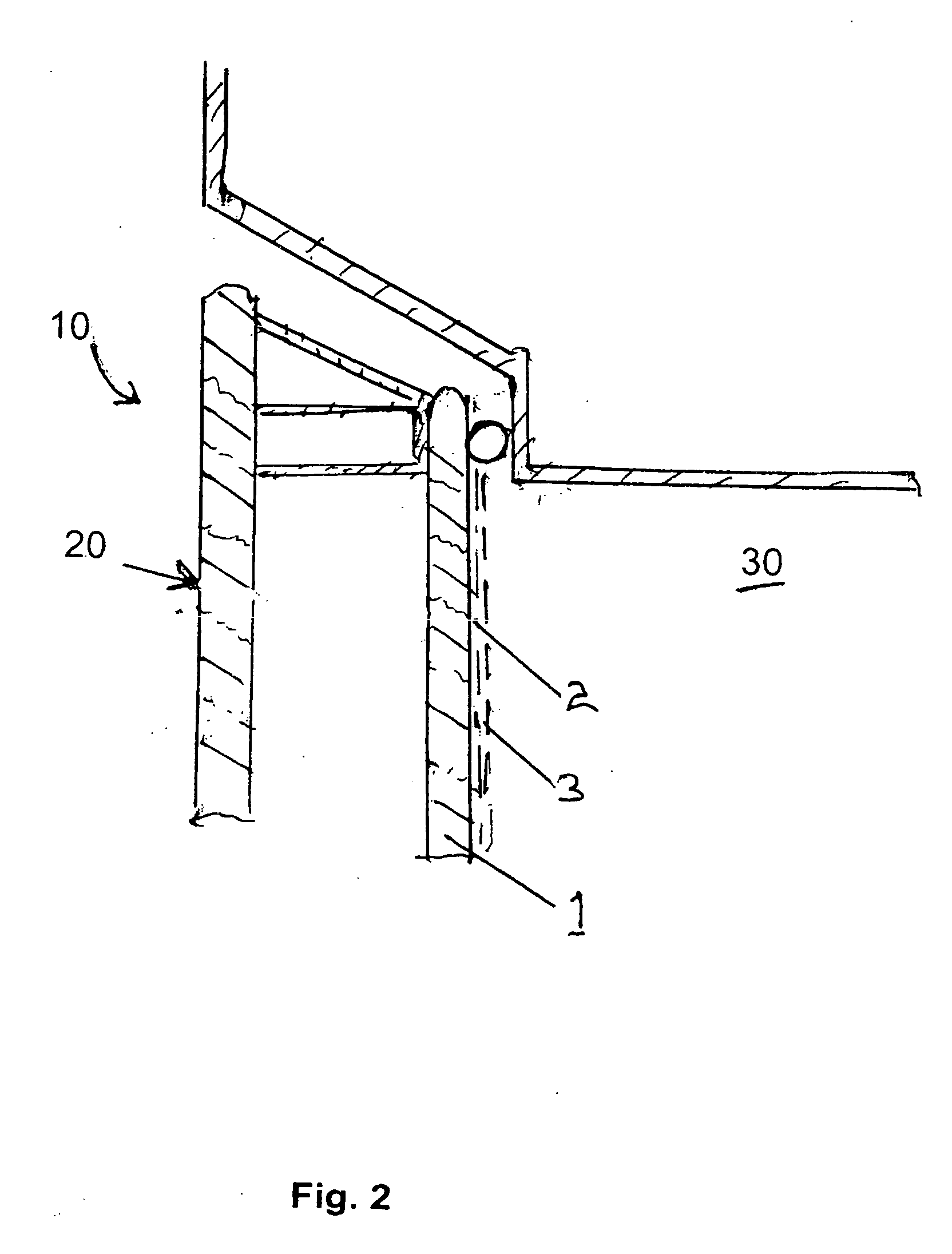
[0023] This inner window pane 1 is exposed to the highest temperatures because it is immediately adjacent to the hot oven muffle or cooking compartment 30 (FIG. 2) during operation of the cooking appliance 10. This is especially true during pyrolytic self-cleaning, in which temperatures of over 500° C. are present in the cooking compartment 30. Because of this reason the inner window pane 1 of the cooking appliance door 20 is made from borosilicate glass, preferably from a pre-stressed borosilicate glass, which has a high resistance to these high temperatures and a small thermal expansion coefficient. The color printing or paint layer 2 is printed on one side of the inner window pane, which is an interior side as shown in this embodiment. The color printing or paint layer 2 can form a colored surface or also letters or symbols, which provide a hint or suggestion for the operator, especially of different cooking programs that the cooking appliance can perform. The color printing or p...
PUM
| Property | Measurement | Unit |
|---|---|---|
| Thickness | aaaaa | aaaaa |
| Electrical resistance | aaaaa | aaaaa |
| Scratch resistance | aaaaa | aaaaa |
Abstract
Description
Claims
Application Information