
Electrical power connector

a technology of electrical connectors and power plugs, applied in the direction of coupling device connections, emergency protective circuit arrangements, coupling device details, etc., can solve the problems of inability to supply control current at zero crossing, heat and fire, and easy failure of line voltage electrical connectors, etc., to achieve the effect of not excessive hea

Inactive Publication Date: 2005-05-05
WEISS INSTR
View PDF8 Cites 14 Cited by
  • Summary
  • Abstract
  • Description
  • Claims
  • Application Information

AI Technical Summary

Benefits of technology

[0004] An electrical connector includes a control circuit for driving a solid state switch such as a triac. The control circuit supplies ample current only at the zero crossing for a short duration of the AC cycle. In one embodiment a current limiting resistor and capacitor are employed in the control circuit to provide a phase shift to drive the triac. Once conduction occurs the control circuit is shorted so that no current is conducted to the triac gate and thus the control circuit does not heat excessively even in high current applications.
[0005] It is an object of the invention to prevent arcing in an alternating current power connector which limits the heat generated in doing so.

Problems solved by technology

Line voltage electrical connectors are susceptible to failure due to arcing when the contact between live parts is insufficient to carry the current.
Over time the arcing between mating connectors will degrade the contacts and carbon residue will form a high resistance that may result in heat and fire.
These approaches cannot supply control current at the zero crossing.
A non-continuous current results in a noisy power supply for the appliance to be powered.

Method used


Image

  • Electrical power connector
  • Electrical power connector
  • Electrical power connector

Examples


Embodiment Construction

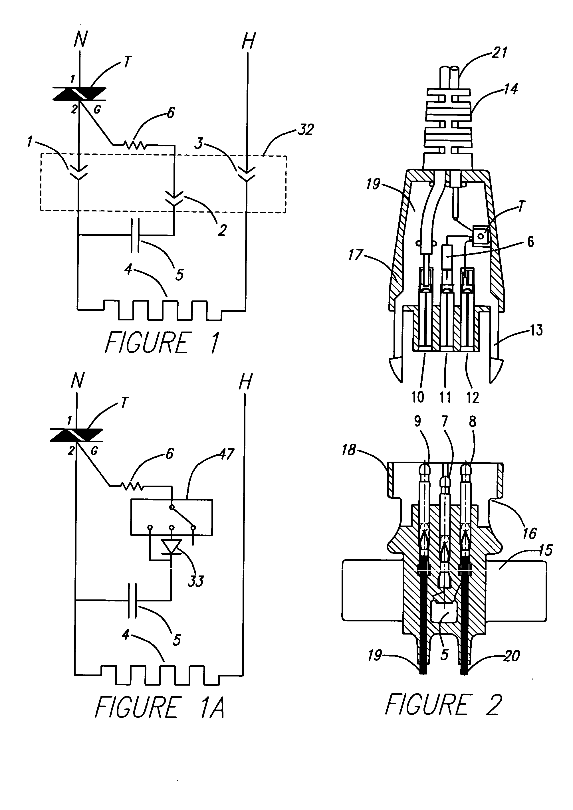
[0016] Referring to FIG. 1, a preferred embodiment of the invention will now be discussed. The load 4 is a resistance heating wire commonly used in heating pads. The power is switched on by a solid-state switch such as a triac, T, and is actively switched on every half cycle of a 60 Hertz 120 volt alternating current power source. The heating wire 4 has a resistance of 300 ohms and is 48 watts under full power. The triac T has a 1 amp rating and is preferably of the sensitive gate type requiring only 5 mA to turn on when supplied at the zero crossing of the AC supply voltage. The triac is shown on the neutral side of the supply. An alternate configuration with the triac on the hot, 120 VAC, side is also suitable. The heating pad controller, not shown, also switches the power on the neutral polarity. When 120 VAC is applied between the supply N and H, the power is not instantly turned on until sufficient gate current is introduced to the triac control gate TG which will occur at the ...


PUM


Abstract

An alternating electrical power connector uses a control circuit to drive a solid state switch controlling power to an appliance without the possibility of arcing, the control circuit is configured to use very low power and operates without generating heat by providing control current only at the zero crossing.

Description

FIELD OF THE INVENTION [0001] The invention relates to electrical power plugs and receptacles that prevent arcing when contact engagement is not sufficient to carry current. BACKGROUND INFORMATION [0002] Line voltage electrical connectors are susceptible to failure due to arcing when the contact between live parts is insufficient to carry the current. Over time the arcing between mating connectors will degrade the contacts and carbon residue will form a high resistance that may result in heat and fire. [0003] One approach to overcome this problem is to employ a control circuit that couples to the power mains after sufficient engagement of the high current carrying contacts is made. The control circuit provides a small current to a thruster or solid state switch such as a triac so that only after the proper engagement is made, full power is applied. U.S. Pat. No. 4,853,823 (Arechavaleta et al.) discloses an electrical receptacle that senses the full contact engagement with a momentar...

Claims


Application Information

Patent Timeline
Patent Type & Authority Applications(United States)
IPC IPC(8): H01R13/66H01R13/703
CPCH01R13/665H01R2103/00H01R24/28H01R13/7038
Inventor WEISS, JOHNLIAO, KUANG PU
Owner WEISS INSTR
Learn More