Dynamic pressure thrust bearing part and method of manufacturing dynamic pressure thrust bearing part

Inactive Publication Date: 2005-05-05
RELIAL CORP
View PDF6 Cites 21 Cited by
  • Summary
  • Abstract
  • Description
  • Claims
  • Application Information

AI Technical Summary

Benefits of technology

[0029] According to the present invention, it has been found that (a) The load of rotation largely depends on the size of the opposing area of the dynamic pressure generating projection pattern and the 
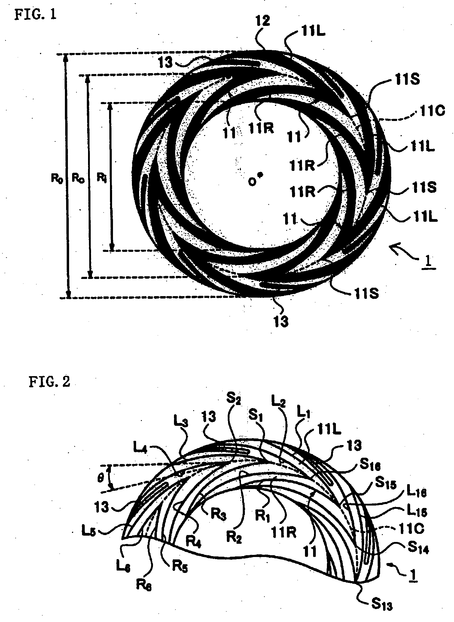
mating part having the bearing space formed therebetween, (b) If considering an object is to generate dynamic pressure, it is neither necessary to make the distance between L1 and L16 larger toward the outer side of the annular ring, nor necessary to make the distance between L1 and L16 larger than the distance between R1 and R16, (C) If considering an object is to generate the dynamic pressure, only the contour part may cross the flow of the fluid at angle θ, to collect the fluid in the central line, and therefore the curves of the other contour parts may be arbitrary in principle, (d) Only the contour part that functions to collect the fluid in the central line is made to cross the flow of the fluid at a predetermined angle, and by making the width of the belt-like part approximately constant, for example, by making it constant with the smallest width capable of maintaining the shape and performing pattern machining (first feature), the area of the projection pattern can be made smaller than the area of the recess pattern (second feature), and as a result, the opposing area of the dynamic pressure generating projection pattern and the mating part having the bearing space formed therebetween can be made smaller than the conventional one, thereby allowing the consumption power to be reduced by an amount of the area thus made to be smaller, (e) Specifically, the dynamic pressure generating pattern may be constituted as described in feature 3 to feature 4.
[0030] In addition, by making the area of the dynamic pressure projection pattern smaller, an approximately belt-like splash preventing projection pattern having a contour shape to act for pulling the liquid supposed to be splashed to the outside through a centrifugal force generated through rotation is formed separately from the dynamic pressure generating pattern (fifth feature), thereby extremely increasing the degree of freedom in terms of designing.
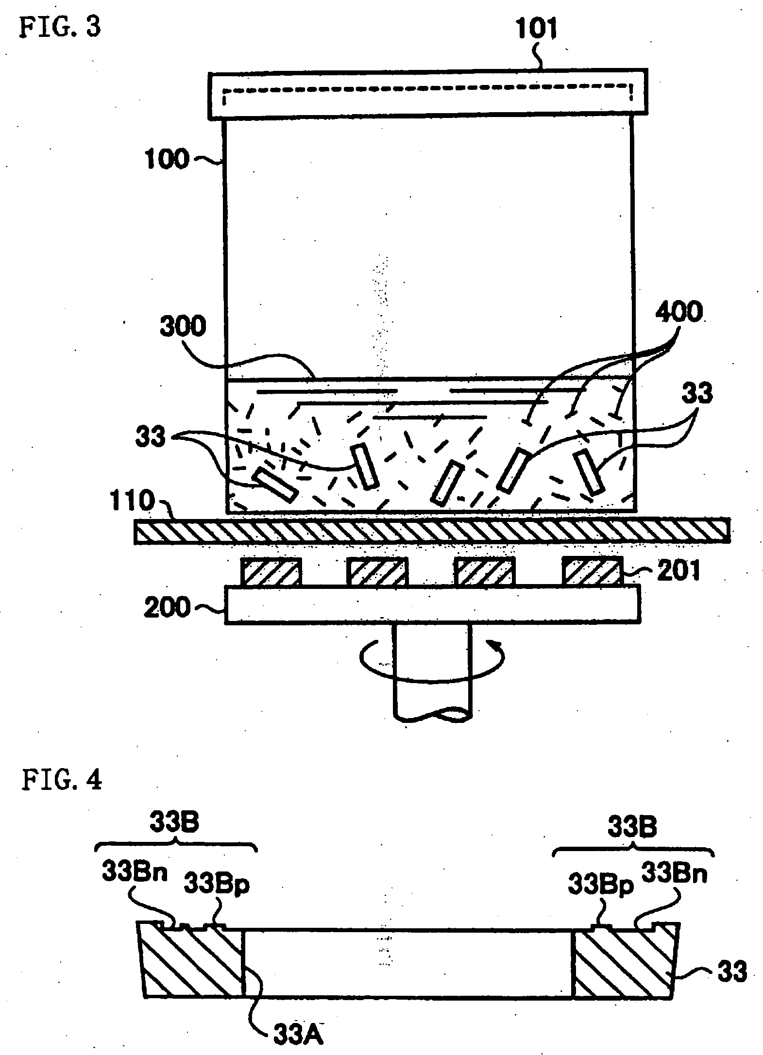
[0031] Also, in the above-described feature, it has been found that an action effect can be obtained in such a way tha

Problems solved by technology

Therefore, manufacture of the dynamic pressure bearing part having a dynamic pressure generating bearing member and a dynamic pressure bearing member as the mating member requires high machining accuracy.
Meanwhile, for example, while modification of HDD and new development have been progressed, the bearing device of the HDD spindle motor has been subjected to further tough requirements.
The aforementioned conventional dynamic thrust bearing part can not necessarily sufficiently respond to such a requirement.
However, it has been found that the dynamic bearing

Method used


Image

  • Dynamic pressure thrust bearing part and method of manufacturing dynamic pressure thrust bearing part
  • Dynamic pressure thrust bearing part and method of manufacturing dynamic pressure thrust bearing part
  • Dynamic pressure thrust bearing part and method of manufacturing dynamic pressure thrust bearing part

Examples


Example

[0048]FIG. 1 is a view illustrating a dynamic pressure thrust bearing part according to an embodiment of the present invention, and FIG. 2 is an explanatory view of profile curves of dynamic pressure generating projection patterns 11. The dynamic pressure thrust bearing part according to the embodiments of the present invention will be explained with reference to the embodiments hereafter. A dynamic pressure thrust bearing part 1 is constituted in such a manner that a plate material such as aluminum metal, etc., is machined into an annular form, and eight dynamic pressure generating projection patterns 11 and splash preventing projection patterns 13 are formed on the surface of one of the annular body, so as to be circular symmetrical against the center point of the annular body, while the other part other than the part having dynamic pressure generating projection patterns 11 and the splash preventing projection patterns 13 has recess patterns 12.

[0049] The dynamic pressure genera...


PUM

PropertyMeasurementUnit
Volumeaaaaaaaaaa
Electrical conductanceaaaaaaaaaa
Pressureaaaaaaaaaa

Abstract

To manufacture a dynamic pressure bearing part at a low cost, capable of making consumption power small by reducing a load of rotation and having remarkable durability while ensuring small size and high performance. Dynamic pressure generating projection parts 21 are formed on the surface of an annular ring, which is a material of the dynamic pressure bearing part having a profile shape of a herringbone type having a first belt-like part 11L and a second belt-like part 11R which are branched out from a tip end 21S to a rear end so as to form a double fork shape, and widths of which are made to be approximately fixed widths. The material of the dynamic pressure bearing part is subjected to a magnetic barrel polish processing to obtain the dynamic pressure thrust bearing part.

Description

BACKGROUND OF THE INVENTION [0001] 1. Field of the Invention [0002] The present invention relates to a dynamic pressure thrust bearing part forming a dynamic pressure generation part of a dynamic pressure bearing device used as a thrust bearing of a rotation part of a disk rotary type memory device such as a driving device including a hard disk drive (HDD) and a digital versatile disk (DVD), and a polygon mirror, etc., and a method of manufacturing the dynamic pressure bearing part. [0003] 2. Description of the Related Art [0004] Generally, a dynamic pressure bearing device functions to rotatably support a rotating shaft by providing dynamic pressure to an actuating fluid, which is filled in a space between a rotation part including a rotating shaft and a stationary part, by using rotating force of the rotating shaft, with the rotation part floated over the stationary part by the dynamic pressure. The dynamic pressure bearing device includes a device operating as a journal bearing a...

Claims


Application Information

Patent Timeline
IPC IPC(8): B23H9/00B24B31/10F16C17/04F16C33/10F16C33/14G11B19/20
CPCB23H9/00B23H2200/10B24B31/102F16C17/026F16C2370/12F16C33/107F16C33/14G11B19/2018F16C17/045F16C2226/40F16C2220/70F16C2220/60F16C2223/06F16C2226/18
Inventor SATOH, KIMIO
Owner RELIAL CORP
Why Eureka
Try Eureka