
Pallet stacker system

a pallet and stacking technology, applied in the field of loaded pallets, can solve the problems of time-consuming, dangerous and time-consuming system for moving and stacking pallets, and the pallet carrying a full load can be very large and heavy, and achieve the effects of safe work environment, convenient synchronization, and protection against undesired movement of pallet lift carriages

Active Publication Date: 2005-05-05
KOLINAHR SYST
View PDF18 Cites 18 Cited by
  • Summary
  • Abstract
  • Description
  • Claims
  • Application Information

AI Technical Summary

Benefits of technology

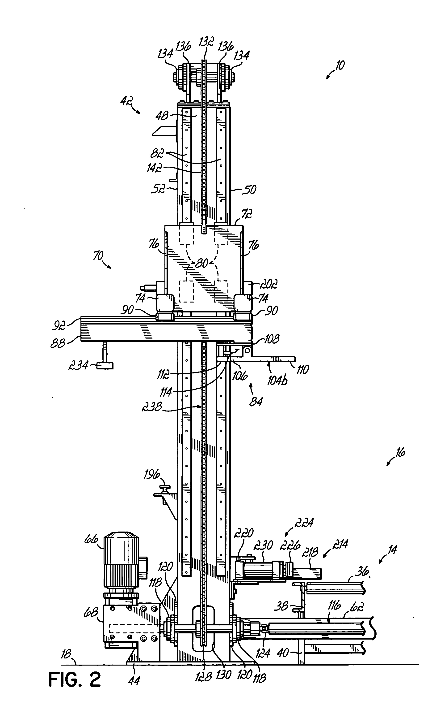
[0015] According to another aspect of the present invention, the pallet stacker uses a drive system and a rotary drive shaft to provide upward and downward movement of the pallet lift carriages. In one embodiment, the drive system has an electric brake motor located near a base of the pallet stacker which simplifies maintenance of the system. The drive system further has a variable frequency drive controller for controlling operation of the electric brake motor. In one embodiment, the drive shaft is segmented into multiple drive shaft sections, with the drive shaft sections coupled to each other through universal joints. This allows the pallet stacker of the present invention to be readily installed and operated at locations where the floor at the pallet stacker is uneven.
[0017] According to still another aspect of the present invention, a spring-loaded chain tensioner is provided to tension the drive chains about their respective pairs of drive and driven sprockets. The chain tensioner, while properly tensioning the drive chains about their respective pairs of drive and driven sprockets, provides sufficient “play” so that the drive chains are capable of jumping their respective drive sprockets. In this way, the vertical positions of the pallet lift carriages may be readily synchronized. A sensor is associated with each chain tensioner and is operable to detect a change in the configuration of the chain tensioner which indicates that pallet stacker has jammed. The sensor is electrically coupled to a programmable logic controller (PLC) of the pallet stacker and causes the PLC to stop operation of the pallet stacker when a jam condition is detected.
[0018] According to another aspect of the present invention, the pallet stacker has a locking mechanism associated with each of the pallet lift carriages in order to provide a safe work environment for those in proximity to the pallet stacker and to guard against undesired movement of the pallet lift carriages due to motor malfunction.
[0020] According to yet another aspect of the present invention, a photo eye sensor is provided to detect the height of the second loaded pallet approaching the pallet stacker and causes the pallet stacker to stop continued upward movement of the first loaded pallet when the pallet lift carriages are located a predetermined distance above the sensed height of the incoming second loaded pallet. By sensing the height of the incoming second loaded pallet, and moving the pallet lift carriages only to a height sufficient to clear the top of the second loaded pallet, the pallet stacker minimizes inefficient movement of the pallet lift carriages during the pallet stacking operation.

Problems solved by technology

Of course, a pallet carrying a full load can be very large and heavy and, therefore, difficult, dangerous and time consuming to move within a warehouse, for example.
This system for moving and stacking pallets is time consuming and can be dangerous.
Using a first forklift truck with or without a second forklift truck helping stack loaded pallets requires the time and attention of at least one employee, and is relatively slow.
Because using forklifts requires at least one forklift operator, moving and stacking pallets by this system also is prone to human error.
For example, an operator could have an accident, toppling an upper loaded pallet from a lower loaded pallet on the forklift, and possibly endangering other employees.
This system has a large operating footprint.
And this system also uses significant floor space because of the retractable fork.
In the above mentioned automated systems which are hydraulic powered, maintenance is time consuming, difficult and messy when dealing with hydraulic fluids.
Also, the hydraulic systems are expensive to maintain and require compliance with environmental regulations regarding hydraulic fluid disposal.

Method used


Image

  • Pallet stacker system
  • Pallet stacker system
  • Pallet stacker system

Examples


Embodiment Construction

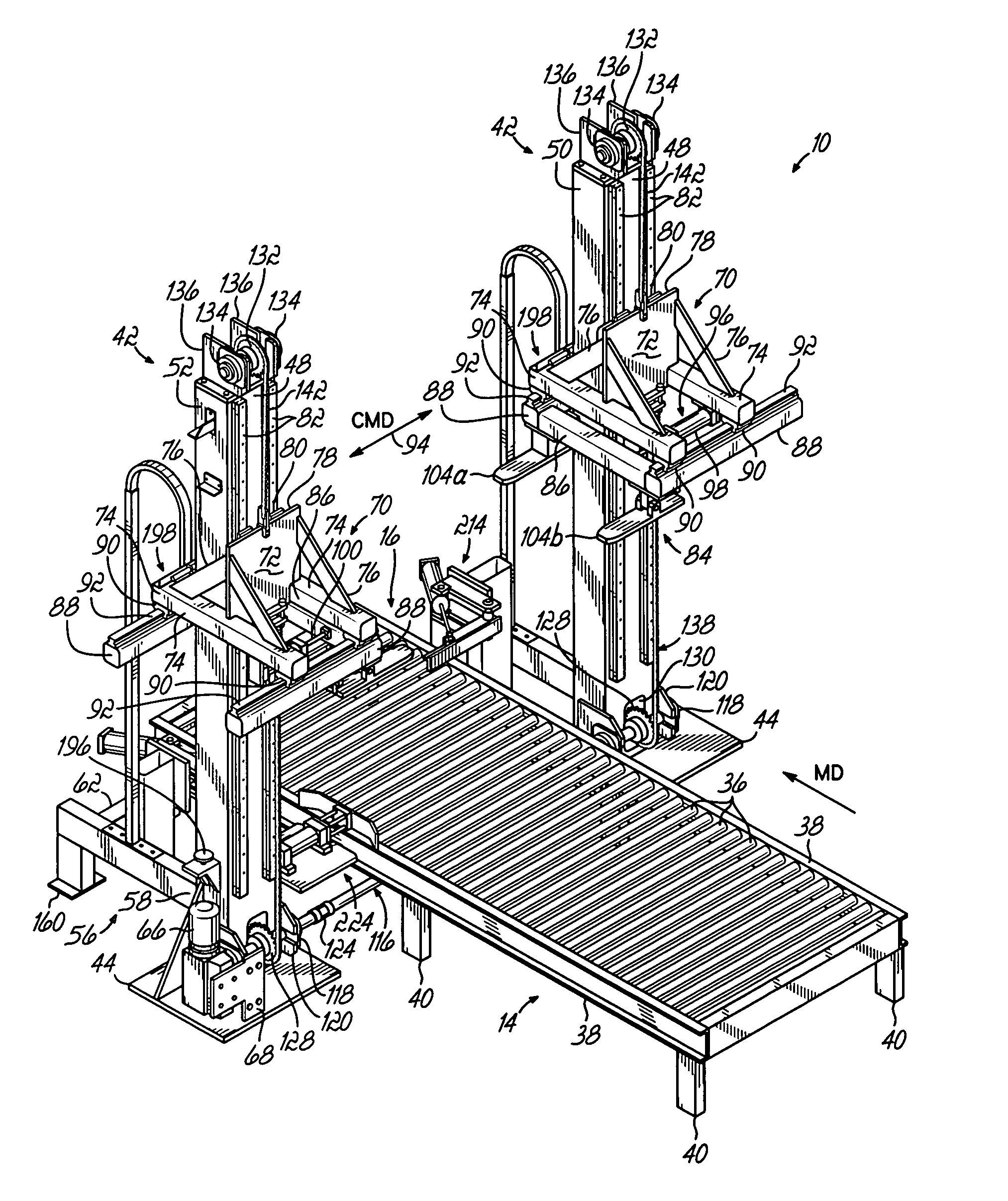
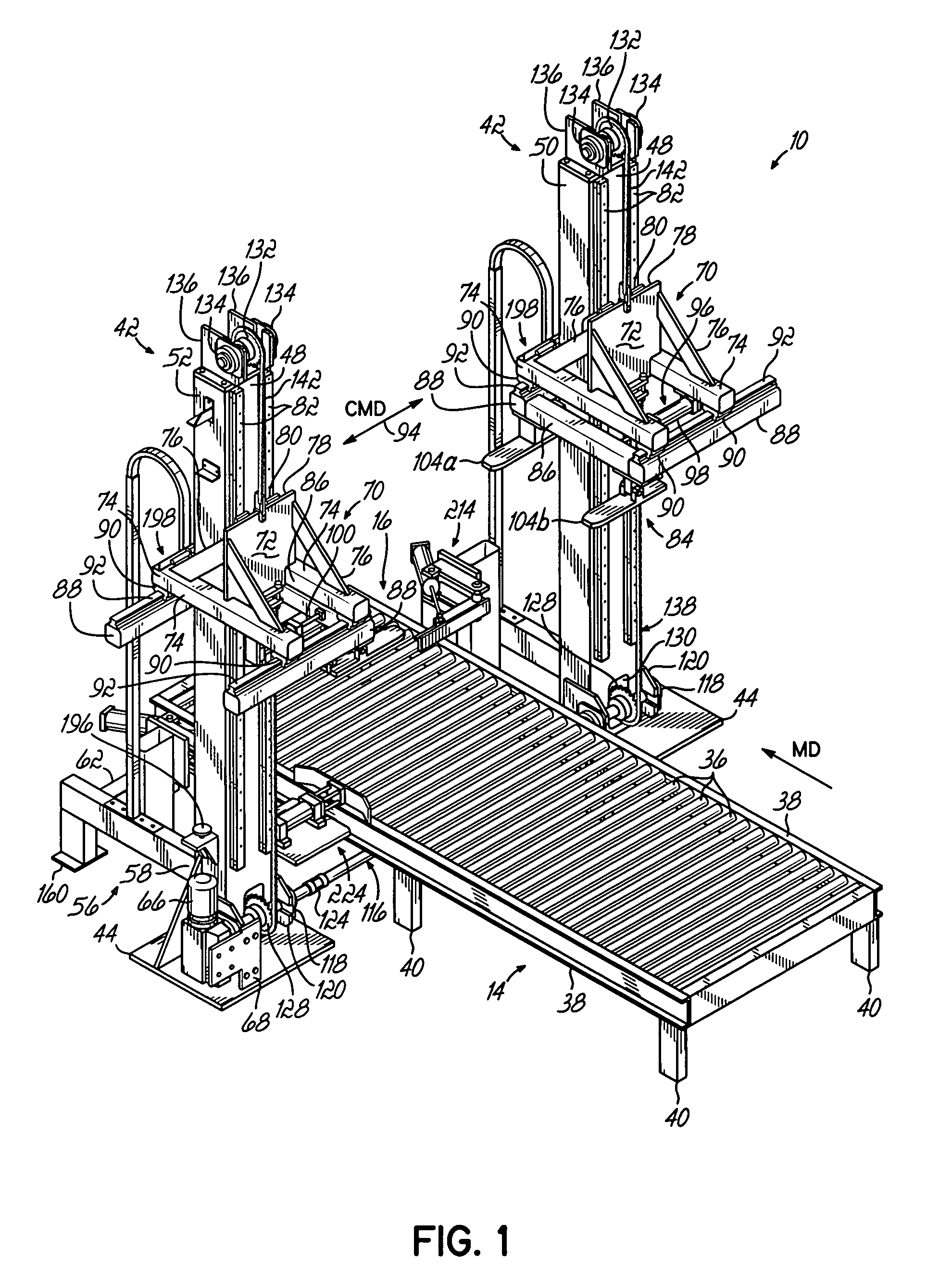
[0034] Referring to FIG. 1, a modular pallet stacker 10 in accordance with the principles of the present invention is provided that is adapted to stack loaded pallets 12 carried to the pallet stacker 10 by a conventional conveyor system 14, the stacker defining a stationary work station 16 relative to floor 18. A typical pallet 20 known in the art generally includes a planar top member (not shown) and a planar base member (not shown) spaced from each other which define a gap 22 (FIGS. 2A and 7) between the top member and bottom member. The pallet stacker 10 of the present invention can handle a wide range of unit load sizes and pallet styles.

[0035] Prior to being transported to the pallet stacker 10, a pallet 20 receives a load 24, for example, plural boxes, polybags or other load items from a pallet loader (i.e., “palletizer”) (not shown). It is the objective of the automatic pallet loader to stack a load 24 on each pallet 20 having a preferred load height H and a preferred load i...


PUM

PropertyMeasurementUnit
heightaaaaaaaaaa
chain tensionaaaaaaaaaa
heightaaaaaaaaaa

Abstract

A method and apparatus for stacking first and second loaded pallets includes a pallet stacker that defines a stationary stacking location. A first loaded pallet is conveyed to the stationary stacking location. A pair of pallet lift carriages are vertically adjustable at the stationary stacking location to selectively engage the first loaded pallet and raise it to a temporary holding position. A second loaded pallet is conveyed into vertical registration with the first loaded pallet. The first loaded pallet is then vertically adjusted into stable stacked relation with the second loaded pallet, and the pallet lift carriages disengage the first loaded pallet. The first and second loaded pallets, in stable stacked relation to each other, thereafter are discharged from the stationary stacking location.

Description

[0001] The present application claims the filing benefit of pending U.S. Provisional Application Ser. No. 60 / 516,792, filed Nov. 3, 2003, the disclosure of which is hereby incorporated herein by reference in its entirety.FIELD OF THE INVENTION [0002] The present invention relates generally to loaded pallets and, more particularly, to an improved system for stacking loaded pallets one on top of the other. BACKGROUND OF THE INVENTION [0003] Pallets, e.g., wood pallets, are used to store and transport loads of a vast range of goods. For example, a pallet can be used to transport boxes of goods that have been stacked and stretch wrapped or otherwise secured upon the pallet from a manufacturer to a point of sale. Of course, a pallet carrying a full load can be very large and heavy and, therefore, difficult, dangerous and time consuming to move within a warehouse, for example. And oft times two loaded pallets are stacked one on top of the other for handling time and / or storage efficiency ...

Claims


Application Information

Patent Timeline
Patent Type & Authority Applications(United States)
IPC IPC(8): B65G57/30
CPCB65G57/302
Inventor JENKINS, GARY E.
Owner KOLINAHR SYST
Learn More