Negative pressure supply apparatus

a technology of negative pressure supply and vacuum pump, which is applied in the direction of positive displacement liquid engine, piston pump, machine/engine, etc., can solve the problems of high production cost, complex structure of vane pump, and high negative pressure supplied to pneumatic booster, so as to reduce the size and production cost, simplify the structure of vacuum pump

Inactive Publication Date: 2005-05-05
HITACHI LTD
View PDF5 Cites 9 Cited by
  • Summary
  • Abstract
  • Description
  • Claims
  • Application Information

AI Technical Summary

Benefits of technology

[0013] With the above-described arrangement, the structure of the vacuum pump can be simplified, and it becomes possible to reduce the size and the production cost.

Problems solved by technology

Consequently, the negative pressure supplied to the pneumatic booster is likely to become insufficient.
However, the vacuum pump disclosed in the above-described publication suffers from the following problems.
The vane pump has a complicated structure and a high production cost and is difficult to reduce in size.
Therefore, if the pump is used to obtain a high degree of vacuum required for the pneumatic booster, the load variation increases, and it becomes difficult to perform a smooth operation.

Method used


Image

  • Negative pressure supply apparatus
  • Negative pressure supply apparatus
  • Negative pressure supply apparatus

Examples


first embodiment

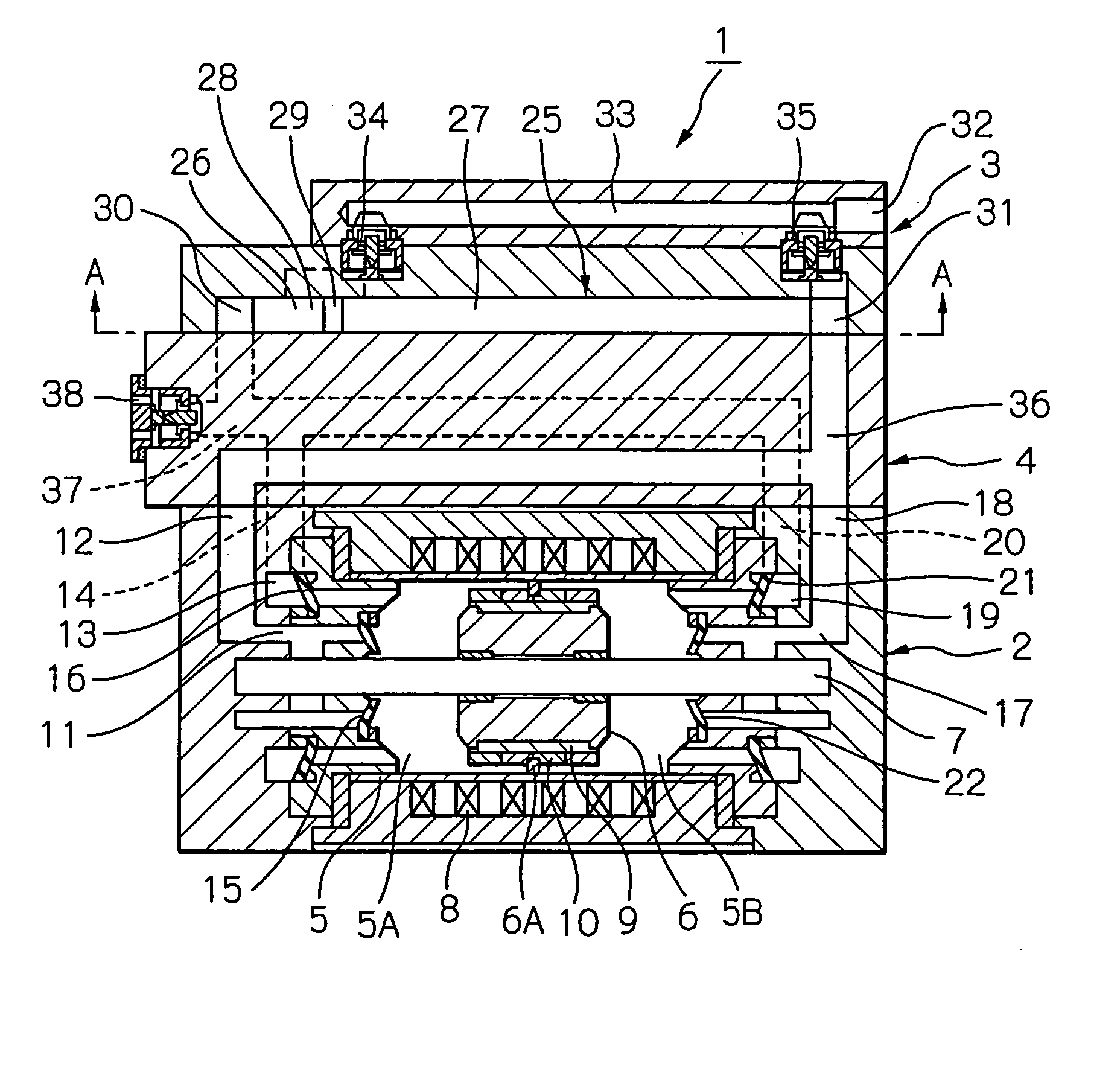
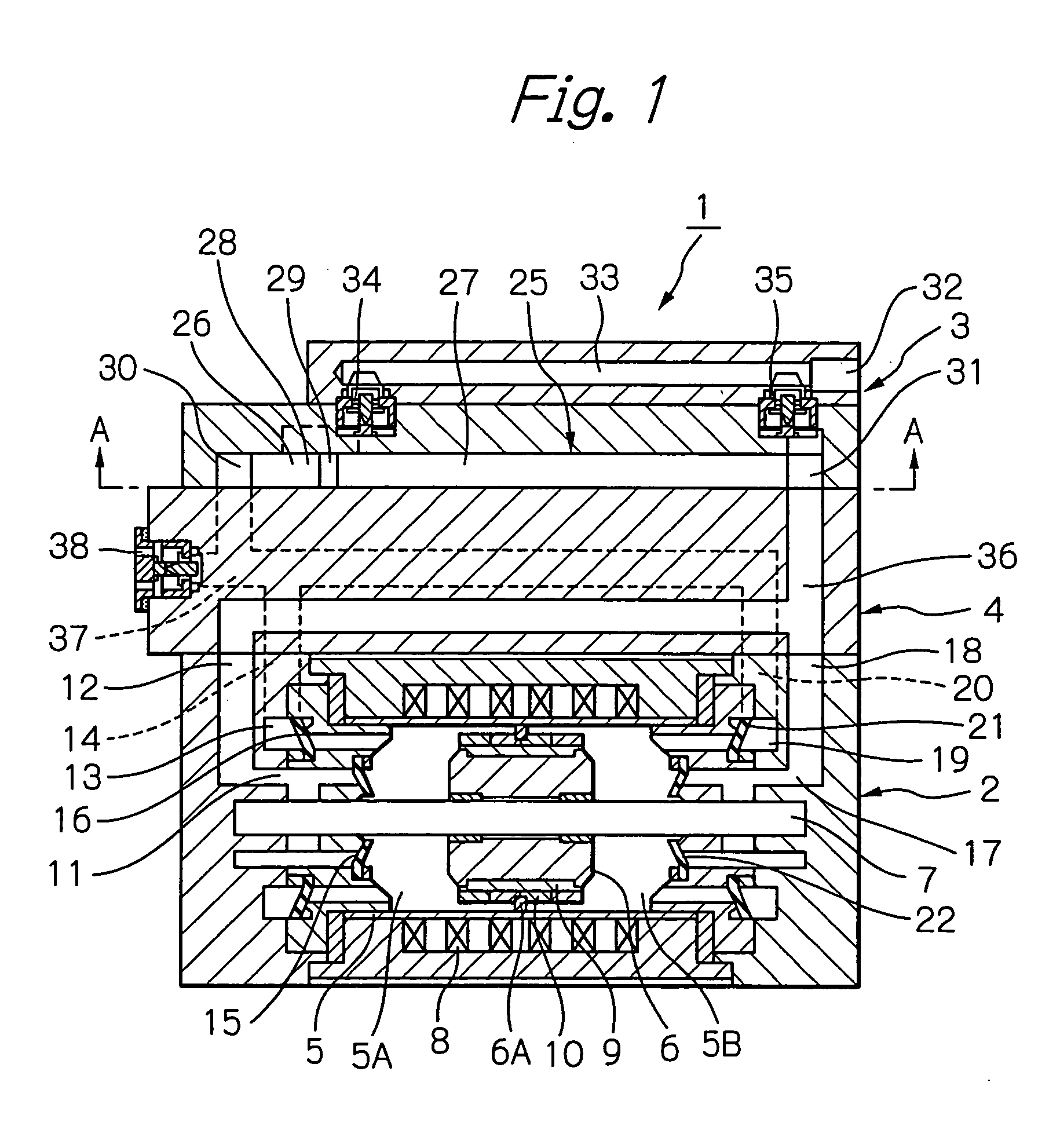
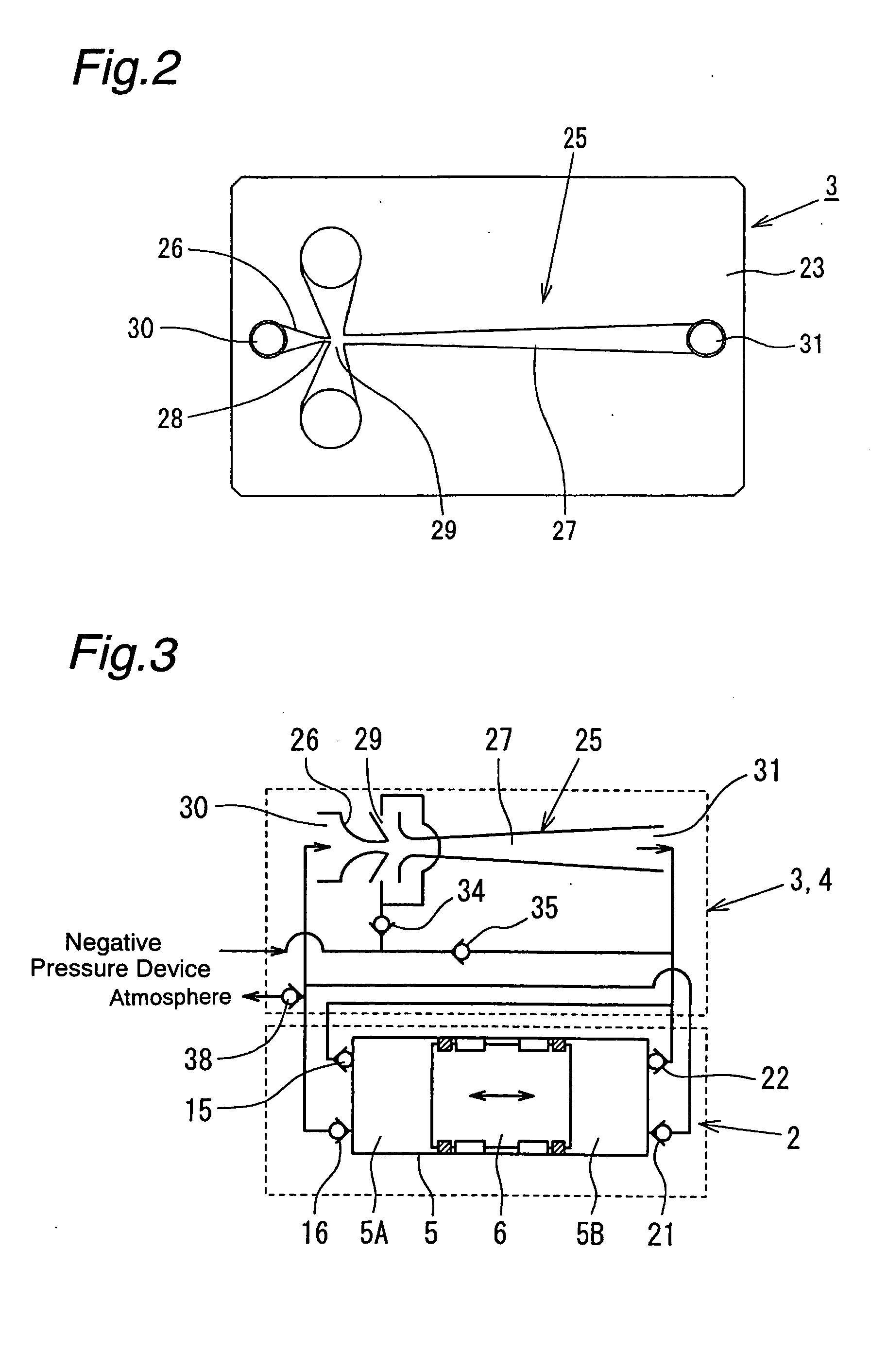
[0020] the present invention will be described with reference to FIGS. 1 to 3. As shown in FIGS. 1 to 3, a negative pressure supply apparatus 1 according to this embodiment has a vacuum pump unit 2 (vacuum pump) and an ejector unit 3, which are joined to each other through a manifold unit 4.

[0021] The vacuum pump unit 2 is a reciprocation-type pump having a piston driven by a moving magnet type linear motor. That is, a piston 6 serving also as a moving member is slidably fitted in a cylinder 5 serving also as a stator. The piston 6 is guided by a rod 7 secured in the cylinder 5. The rod 7 extends along the center axis of the cylinder 5. The cylinder 5 has a plurality of coils 8 installed on an outer peripheral portion thereof. The piston 6 has a magnetic path member 9 and a plurality of magnets 10 installed on an outer peripheral portion thereof. By energizing and thus exciting the coils 8 sequentially, the piston 6 can be moved to reciprocate in the cylinder 5. An annular seal 6A i...

second embodiment

[0031] Next, the present invention will be described with reference to FIGS. 4 and 5.

[0032] It should be noted that, in the following description, members or portions corresponding to those in the foregoing first embodiment are denoted by the same reference numerals, and only portions in which the second embodiment differs from the first embodiment will be explained in detail.

[0033] As shown in FIGS. 4 and 5, in a negative pressure supply apparatus 39 according to this embodiment, the manifold unit 4 in the first embodiment is omitted, and the vacuum pump unit 2 and the ejector unit 3 are joined directly to each other. The first and second suction ports 12 and 18 of the vacuum pump unit 2 communicate with each other through a passage 40 in a hollow rod 7 and thus communicate directly with the outlet passage 31 of the ejector unit 3. The first and second discharge ports 14 and 20 are open directly to the atmosphere. The inlet 30 of the ejector unit 3 communicates with the first disc...


PUM


Abstract

When coils of a vacuum pump unit are excited by energization, a piston equipped with magnets reciprocates in a cylinder. Thus, air is sucked in from an outlet passage of a diffuser of an ejector, and air discharged from the vacuum pump unit is supplied to an inlet of a nozzle of the ejector. Consequently, a fast jet occurs in a throat portion of the nozzle, and a negative pressure of higher degree of vacuum than that of the suction negative pressure of the vacuum pump unit is produced at a vacuum port of the ejector. The negative pressure is supplied from a negative pressure supply port. The ejector can supply a negative pressure of high degree of vacuum while reducing the load on the vacuum pump unit.

Description

BACKGROUND OF THE INVENTION [0001] The present invention relates to a negative pressure supply apparatus for supplying a negative pressure to a pneumatic booster of an automotive brake system, for example. [0002] In general, an automotive brake system is provided with a pneumatic booster to increase braking force. The pneumatic booster uses the engine intake (negative.) pressure as a negative pressure source. That is, the engine intake (negative) pressure is introduced into a constant-pressure chamber (negative pressure chamber) to produce a differential pressure between the intake pressure and the atmospheric pressure, thereby generating thrust in a power piston to assist the brake system with operating force. [0003] In recent years, automotive engines have been improved to reduce pumping loss in order to meet the demand for lower fuel consumption. Accordingly, the engine intake (negative) pressure is tending to decrease. Consequently, the negative pressure supplied to the pneumati...

Claims


Application Information

Patent Timeline
Patent Type & Authority Applications(United States)
IPC IPC(8): F04B35/04F04B41/06F04F5/20
CPCF04B35/045Y10T137/2213F04F5/20F04B41/06
Inventor IKEDA, JUNICHI
Owner HITACHI LTD
Why Eureka
Try Eureka