Method and apparatus for using FPGA technology with a microprocessor for reconfigurable, instruction level hardware acceleration

a microprocessor and instruction technology, applied in the field of microprocessors, can solve the problems that applications cannot take advantage of hardware acceleration or resource sharing provided by the coprocessor, and achieve the effect of reducing the space and flexibility of the chip comprising the coprocessor and the processor

Active Publication Date: 2005-05-05
IBM CORP
View PDF17 Cites 42 Cited by
  • Summary
  • Abstract
  • Description
  • Claims
  • Application Information

AI Technical Summary

Benefits of technology

[0005] A method for dynamically programming Field Programmable Gate Arrays (FPGA) in a coprocessor, the coprocessor coupled to a processor, includes: beginning an execution of an application by the processor; receiving an instruction from the processor to the coprocessor to perform a function for the application; determining that the FPGA in the coprocessor is not programmed with logic for the function; fetching a configuration bit stream for the function; and programming the FPGA with the configuration bit stream. In this manner, the FPGA is programmable “on the fly”, i.e., dynamically during the execution of an application. The hardware acceleration and resource sharing advantages provided by the FPGA can be utilized more often by the application. Logic flexibility and space savings on the chip comprising the coprocessor and processor are provided as well.

Problems solved by technology

However, if during execution of the application, the application requests a function not programmed into the FPGA 110, then the application cannot take advantage of the hardware acceleration or the resource sharing provided by the coprocessor 104, even if the requested function had existed in the library of functions available for programming the FPGA 110.

Method used


Image

  • Method and apparatus for using FPGA technology with a microprocessor for reconfigurable, instruction level hardware acceleration
  • Method and apparatus for using FPGA technology with a microprocessor for reconfigurable, instruction level hardware acceleration
  • Method and apparatus for using FPGA technology with a microprocessor for reconfigurable, instruction level hardware acceleration

Examples


Embodiment Construction

[0013] The present invention provides a method and apparatus for dynamically programming Field Programmable Gate Arrays (FPGA). The following description is presented to enable one of ordinary skill in the art to make and use the invention and is provided in the context of a patent application and its requirements. Various modifications to the preferred embodiment will be readily apparent to those skilled in the art and the generic principles herein may be applied to other embodiments. Thus, the present invention is not intended to be limited to the embodiment shown but is to be accorded the widest scope consistent with the principles and features described herein.

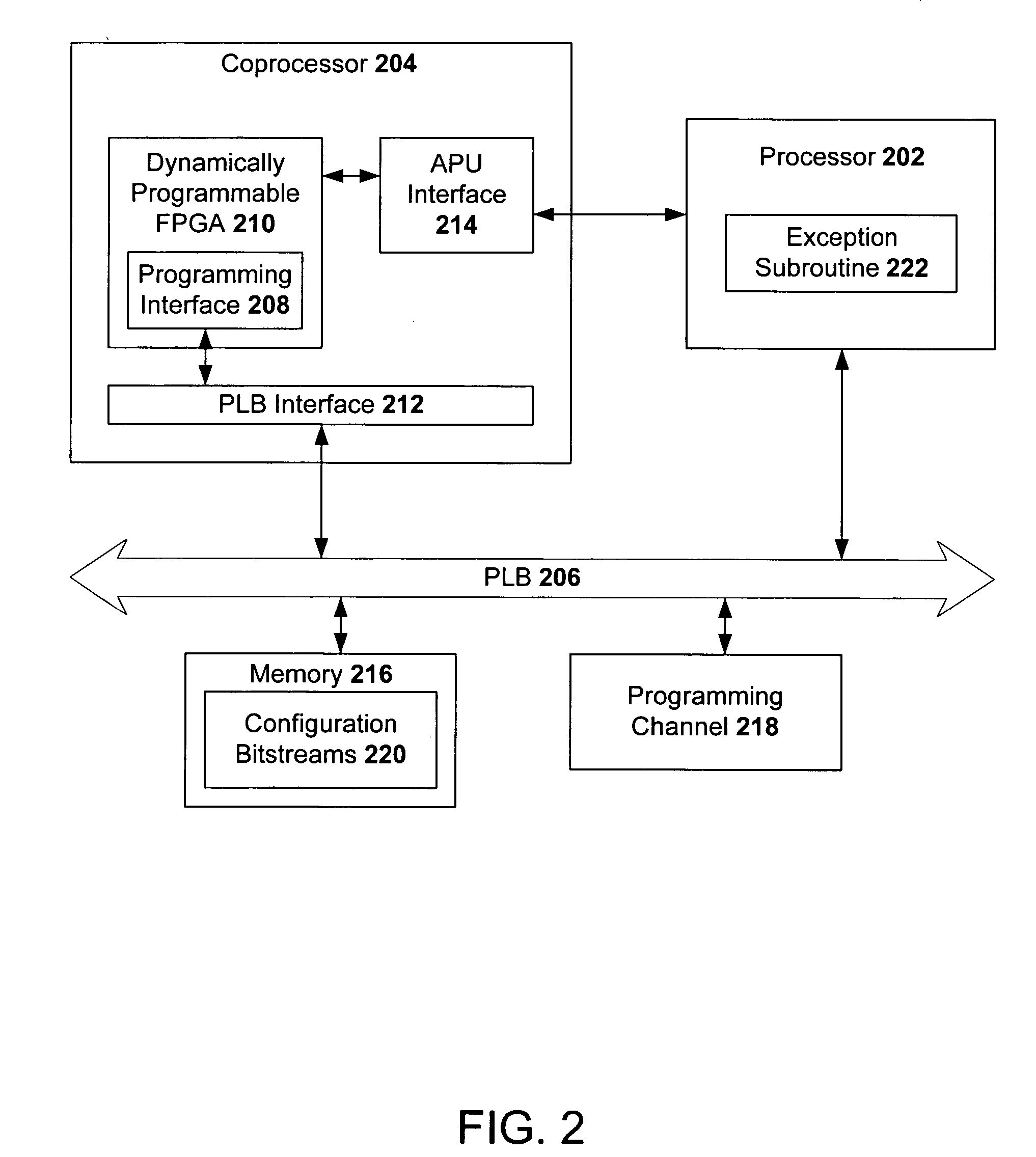
[0014] To more particularly describe the features of the present invention, please refer to FIGS. 2 through 7 in conjunction with the discussion below.

[0015]FIG. 2 illustrates a preferred embodiment of an apparatus for dynamically programming an FPGA in accordance with the present invention. The apparatus comprises a mai...


PUM


Abstract

A method for dynamically programming Field Programmable Gate Arrays (FPGA) in a coprocessor, the coprocessor coupled to a processor, includes: beginning an execution of an application by the processor; receiving an instruction from the processor to the coprocessor to perform a function for the application; determining that the FPGA in the coprocessor is not programmed with logic for the function; fetching a configuration bit stream for the function; and programming the FPGA with the configuration bit stream. In this manner, the FPGA are programmable “on the fly”, i.e., dynamically during the execution of an application. The hardware acceleration and resource sharing advantages provided by the FPGA can be utilized more often by the application. Logic flexibility and space savings on the chip comprising the coprocessor and processor are provided as well.

Description

FIELD OF THE INVENTION [0001] The present invention relates to microprocessors, and more particularly, to the configuration of coprocessors associated with microprocessors. BACKGROUND OF THE INVENTION [0002] The use of Field Programmable Gate Arrays (FPGA) on an Application Specific Integrated Circuit (ASIC) chip and / or a system-on-a-chip to provide instruction level hardware acceleration and resource sharing is known in the art. FIG. 1 illustrates a conventional apparatus utilizing FPGA. The apparatus can be an ASIC, a system-on-a-chip, or some other chip comprising a main processor 102, a coprocessor 104, and a local bus, such as the Processor Local Bus (PLB) 106 developed by International Business Machines Corporation™. Other local buses can also be used, such as the Advanced Micro-Controller Bus Architecture (AMBA) developed by ARM™. The coprocessor 104 comprises FPGA cells 110 and a plurality of interfaces. The interfaces include a programming interface 108, through which the F...

Claims


Application Information

Patent Timeline
Patent Type & Authority Applications(United States)
IPC IPC(8): G06F9/00G06F9/318G06F9/38G06F15/78
CPCG06F9/30181G06F15/7867G06F9/3897G06F9/3877
Inventor DOERING, ANDREAS C.DRAGONE, SILVIOHERKERSDORF, ANDREASHOFMANN, RICHARD G.KUHLMANN, CHARLES E.
Owner IBM CORP
Why Eureka
Try Eureka