[0012] The present invention provides liquid fuel valves for use in the
extreme temperature and pressure conditions of land and air based gas turbine engine applications. The compact valve
package is cooled by a dedicated liquid
coolant circuit circulating relatively low temperature water past critical parts of the valve to provide more consistent operation and reduce coking.
[0014] Dedicated
water supply and return ports are used to connect the valve to a
water supply via suitable lines. Preferably, the water return and supply ports are tangential to the valve chamber so that a swirling motions is effected inside the valve which aids in distributing the
coolant along the interior of the valve and thereby improves
heat transfer.
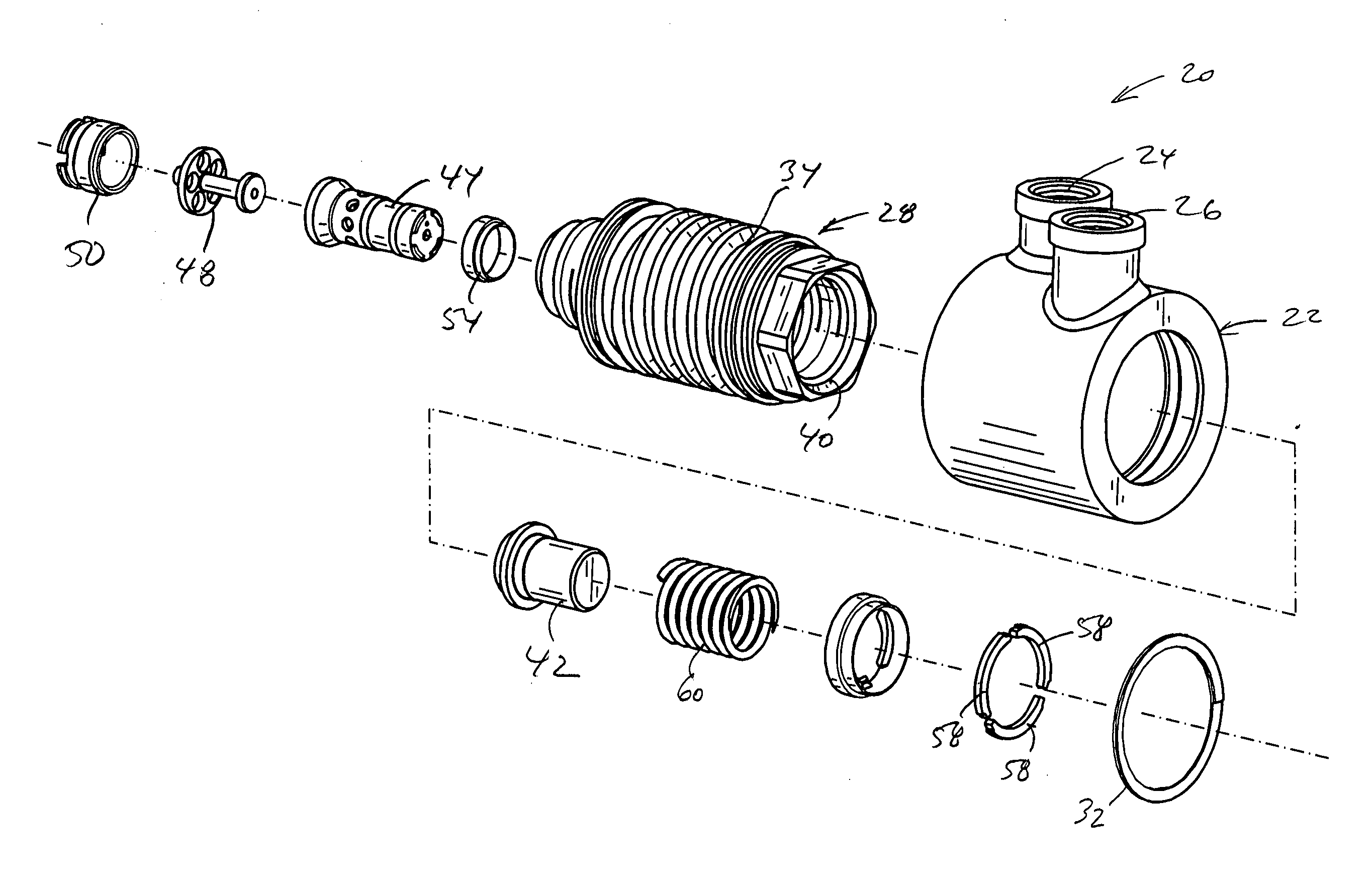
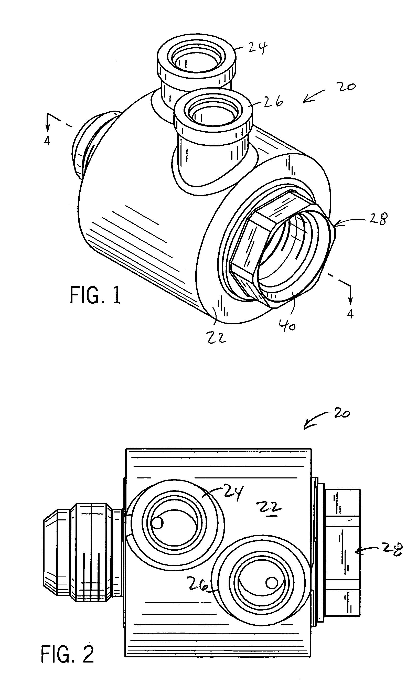
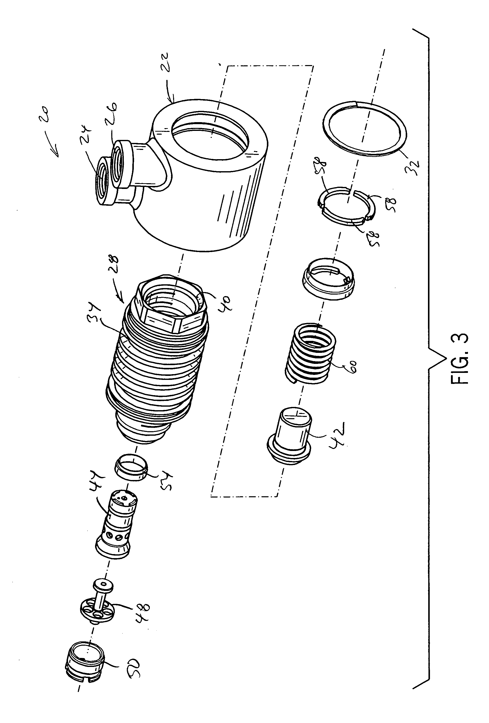
[0018] Thus, in one aspect the present invention provides a
water cooled liquid fuel
check valve. The
check valve can have a
water jacket, having tangential water supply and return ports, that fits over a valve body having a spring biased fuel actuated valve member biased to close off communication between the fuel inlet and outlet ports. The valve body has an annular groove forming the cooling water circuit between the valve body and the
water jacket in communication with the water supply and return ports. The valve can also have a special baffle member with a series of openings, some of which are axially aligned with the
poppet valve member allowing liquid fuel to flow into a primary metering chamber. The baffle member also has radial openings to a stem with an axial passageway leading a portion of the fuel to a Helmhotz type
resonance chamber, which preferably is defined by the interior of the poppet, to dampen pressure oscillations in the exiting fuel flow.
[0020] In yet another aspect, the present invention provides a liquid fuel metering valve with a dedicated fluid
coolant circuit and purge air and / or
distributor sections. The valve includes three isolated flow circuits, namely a liquid fuel circuit, a
cooling fluid circuit and a purge air circuit. In particular, the liquid fuel circuit includes a fuel inlet port, a fuel only section of the valve chamber and an outlet port. The purge air circuit includes an air inlet port, an air only section of the valve chamber and the outlet port. The
cooling fluid circuit includes
cooling fluid supply and return ports for circulating cooling fluid of
proximate the valve member. The coolant circuit is preferably entirely separate passageways, for example having a spiral or
helical section between the valve body and a water jacket. However in a preferred 3-way metering / purge valve construction, the fuel and purge air circuits, preferably share one or more passageways and the outlet port leading to the
combustor(s) while the valve member isolates the air flow form the fuel flow so that these streams do not mix. The valve thus can be operated to meter fuel to the burner
nozzle during sustained liquid fuel operation and alternatively to purge the downstream fuel lines and burners with air to cool them and extricate residual liquid fuel to prevent coking during
shut down and gaseous fuel operation of the turbine.
[0021] In still another aspect, the valve is a fluid cooled combined purge air and distributor valve. In this case, the housing defines the aforementioned three flow circuits as well as a distributor section having a plurality of outlet ports which make up part of the liquid fuel circuit. Also, the liquid fuel circuit preferably includes a plurality of flow orifices disposed within the liquid fuel circuit between the fluid inlet port and an associated one of the plurality of outlet ports. At least one of the flow orifices receives a module that mounts to the valve housing. Each module can define a flow passageway or a plug blocking the flow of liquid fuel through the associated flow orifice. The valve is arranged so that the liquid fuel inlet port is in communication with the plurality of flow orifices when the valve member is in a first, lesser open position and in communication with the plurality of flow orifices and the plurality of outlet ports when the valve member is in a second, fully open position. This arrangement provides at least two benefits. First, it provides for a lesser volume of liquid fuel to flow to the turbine atomizer and burners, for example during light-off. Second, the modules allow the valve to be configured to flow liquid fuel to one or sub-set of burner nozzles designated to begin combustion at light-off.

