Fuel vent assembly with floatless rollover protection

a technology of floatless rollover protection and fuel vent assembly, which is applied in the direction of liquid fuel feeders, machines/engines, combustion air/fuel-air treatment, etc., can solve the problems of failure rate, all mechanical floats, springs and combinations suffer from similar problems, and significant fire hazards, etc., and achieve the effect of being cheap to manufactur

Active Publication Date: 2005-05-12
FCA US
View PDF7 Cites 37 Cited by
  • Summary
  • Abstract
  • Description
  • Claims
  • Application Information

AI Technical Summary

Benefits of technology

[0007] Another object of the present invention is a fuel vent

Problems solved by technology

Because it is undesirably to vent fuel vapor directly into the atmosphere, modern vehicles all employ a vapor recovery system that in its most simplistic form consists of a vent hole in the tank connected via a tube to a vapor recovery canister.
Such a valve is necessary because vapor recovery canisters are inundated by liquid fuel that splashes out of a full fuel tank, and, more

Method used


Image

  • Fuel vent assembly with floatless rollover protection
  • Fuel vent assembly with floatless rollover protection
  • Fuel vent assembly with floatless rollover protection

Examples


Embodiment Construction

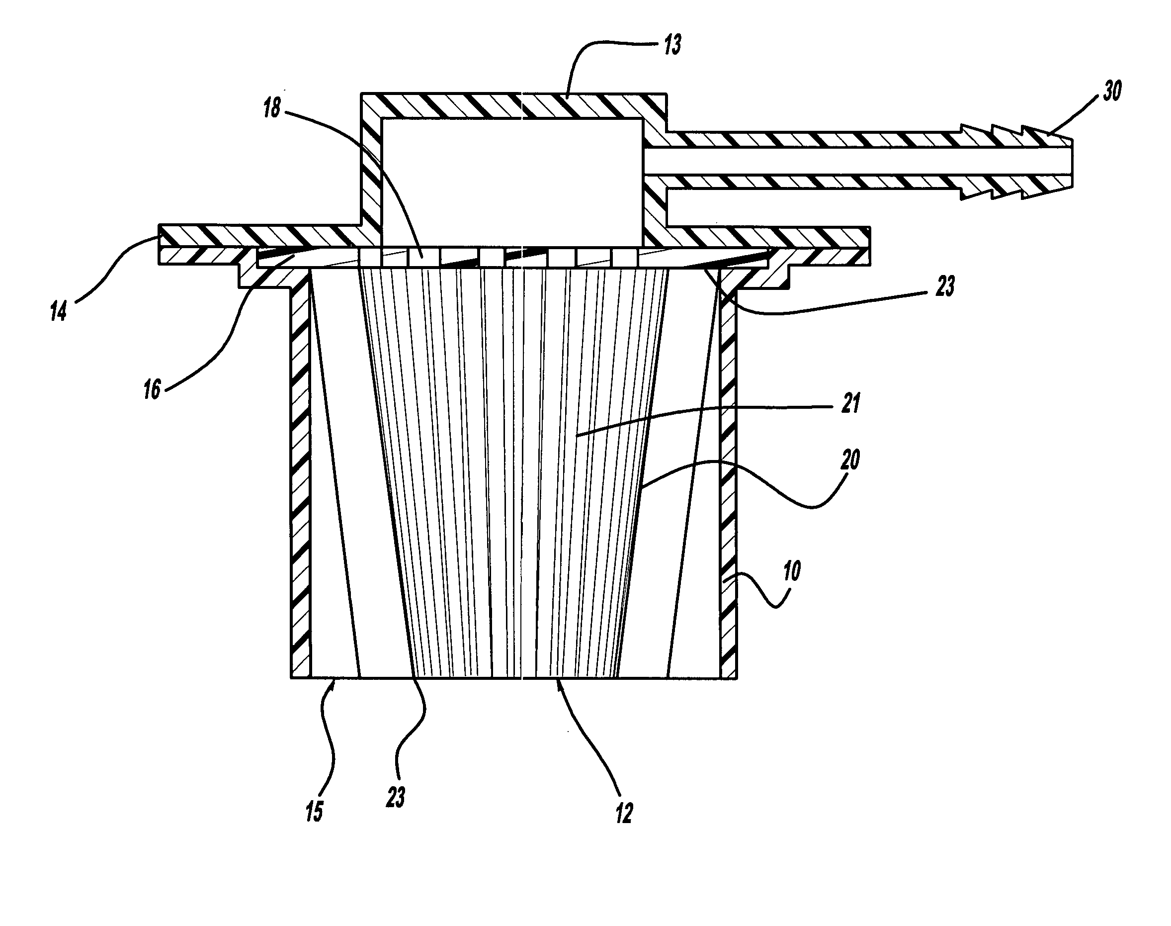
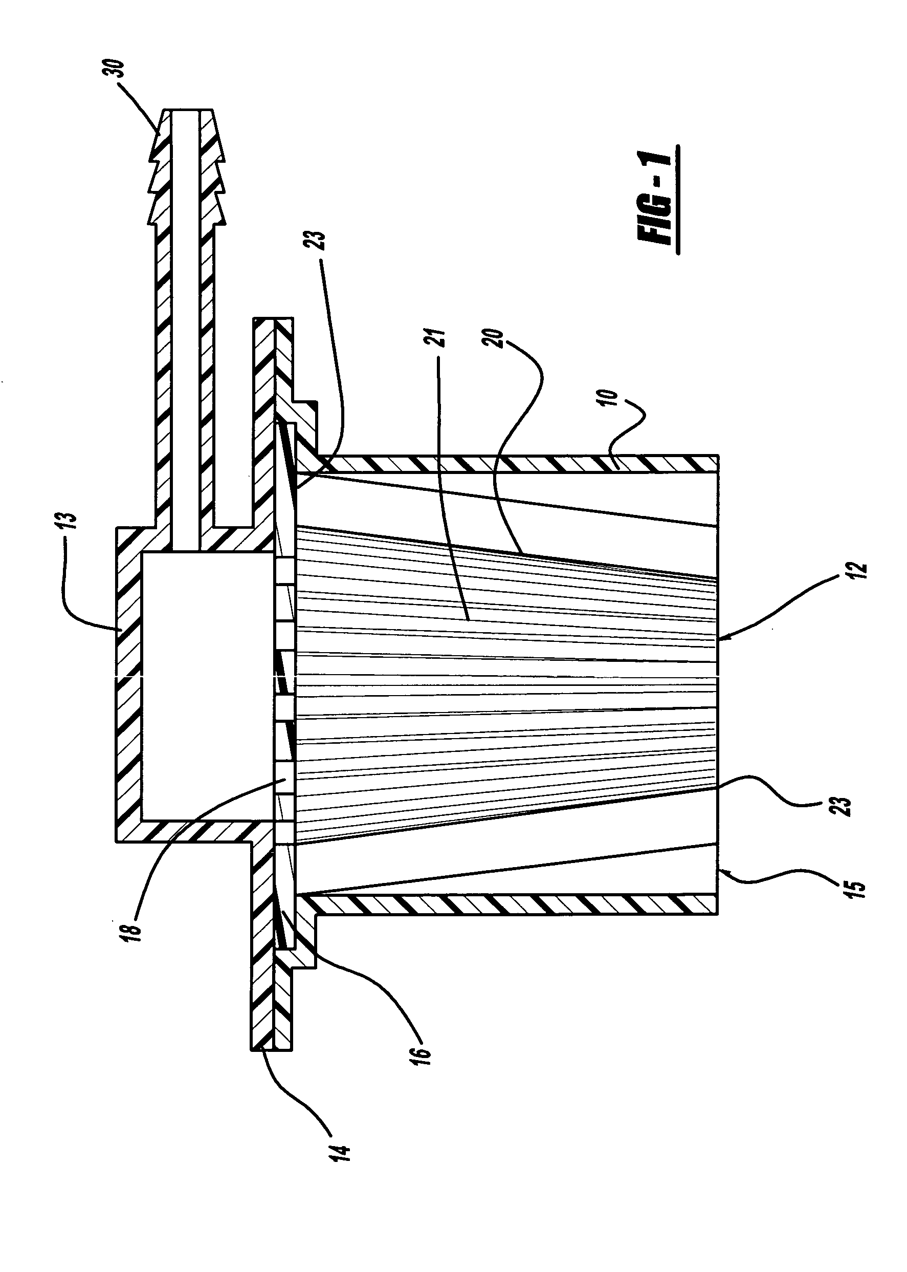
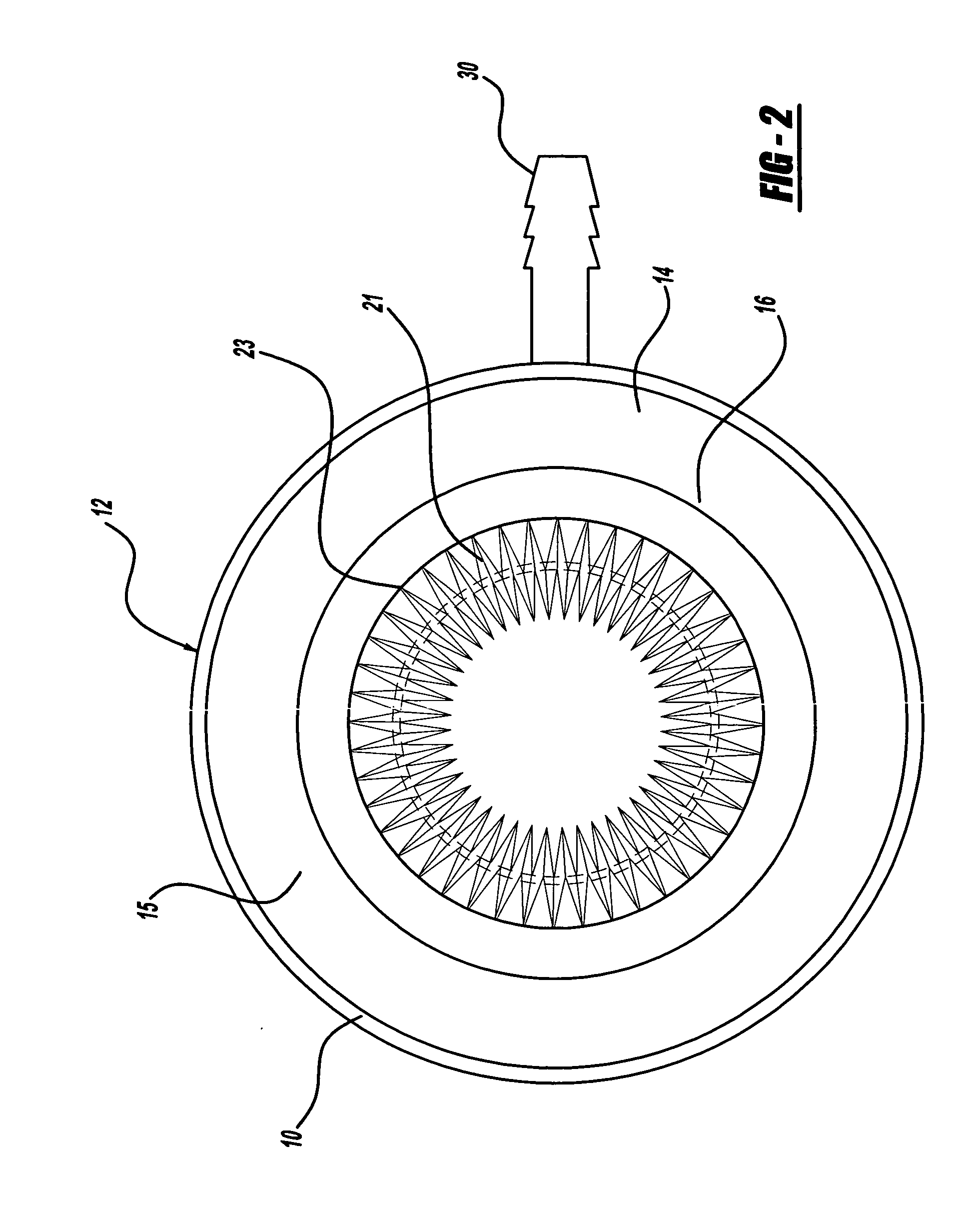
[0011] A valve according to the invention for use between a vehicle fuel tank vent and a vapor recovery canister in a vehicle fuel tank containing liquid fuel represents a major improvement over the prior art because it has no moving parts.

[0012] In its most basic form, a valve according to the present invention comprises a housing formed using the minimum number of injection molded, blow molded, cast, etc. components that are then snapped, bonded, or welded together. A vapor permeable membrane that allows passage of air and fuel vapor, but uses the surface tension of the fluid to prevent its passage is fixed in the housing to block the passage of liquid fuel. The pore size of such material is preferably 0.2 to 5.0 microns; more preferably 0.45 to 0.80 microns; and most preferably 0.45 to 0.80 microns. Preferably, the housing is configured to permit mounting of the vapor permeable membrane so that the membrane is protected from fuel splashing.

[0013] The preferred vapor permeable m...


PUM


Abstract

A valve for use between a vehicle fuel tank vent and a vapor recovery canister in a vehicle fuel tank containing liquid fuel, such a valve comprises: a housing having a fuel tank side and a vapor recovery canister side; and a vapor permeable membrane fixed to the housing to block the passage of liquid fuel.

Description

FIELD OF THE INVENTION [0001] The present invention relates to an improved fuel tank vent assembly. More specifically, the present invention is directed to a vehicle fuel tank vent assembly that has no moving parts and provides a durable, inexpensive, vent that will not permit liquid fuel to leak out of the tank in the case of a vehicle rollover. BACKGROUND OF THE INVENTION [0002] When a vehicle's fuel tank is filled with liquid fuel at the gas station by means of the typical fuel pump nozzle, fuel vapor above the liquid fuel in the interior of the fuel tank is displaced as the fuel level increases. Obviously, this vapor must be vented for the tank to be filled. Because it is undesirably to vent fuel vapor directly into the atmosphere, modern vehicles all employ a vapor recovery system that in its most simplistic form consists of a vent hole in the tank connected via a tube to a vapor recovery canister. [0003] As early vapor recovery systems came into use, it was discovered that a v...

Claims


Application Information

Patent Timeline
IPC IPC(8): B60K15/035F02M25/08
CPCB60K15/03519B60K2015/03276F02M25/0836
Inventor TAXON, MORSE N.
Owner FCA US
Why Eureka
Try Eureka