Touch panel and liquid crystal display apparatus using the same

a technology of liquid crystal display and touch panel, which is applied in the direction of identification means, instruments, static indicating devices, etc., can solve the problems of increasing production costs, difficult to reduce the size and weight of the apparatus on which the touch panel is mounted, and difficult to consistently maintain the electrical connection of a portion, etc., to achieve the effect of reducing the size and weight of the apparatus and low cos

Inactive Publication Date: 2005-05-12
PANASONIC CORP
View PDF7 Cites 159 Cited by
  • Summary
  • Abstract
  • Description
  • Claims
  • Application Information

AI Technical Summary

Benefits of technology

[0024] A touch panel according to the present invention comprises a first transparent substrate having a first transparent electrically conductive film formed on a top face thereof, a second transparent substrate, having a second transparent electrically conductive film formed on a face opposite to the first transparent electrically conductive film, in which an outside of a visible area boundary is fixed by a adhesive layer and an inside thereof is held with a specified space from the first transparent substrate, and a flexible printed-circuit board (FPC) bonded by thermocompression to at least one of the first transparent substrate and the second transpare

Problems solved by technology

However, in the aforementioned conventional touch panel, an area outside visible area boundary 6 of the touch panel, namely, an area of the picture frame, becomes large and, accordingly, there is a problem in that it becomes difficult to reduce a size and weight of an apparatus on which the touch panel is mounted.
There is a problem in that the stress becomes a force for peeling FPC 21 bonded onto both first transparent substrate 1 and second trans

Method used


Image

  • Touch panel and liquid crystal display apparatus using the same
  • Touch panel and liquid crystal display apparatus using the same
  • Touch panel and liquid crystal display apparatus using the same

Examples


embodiment 1

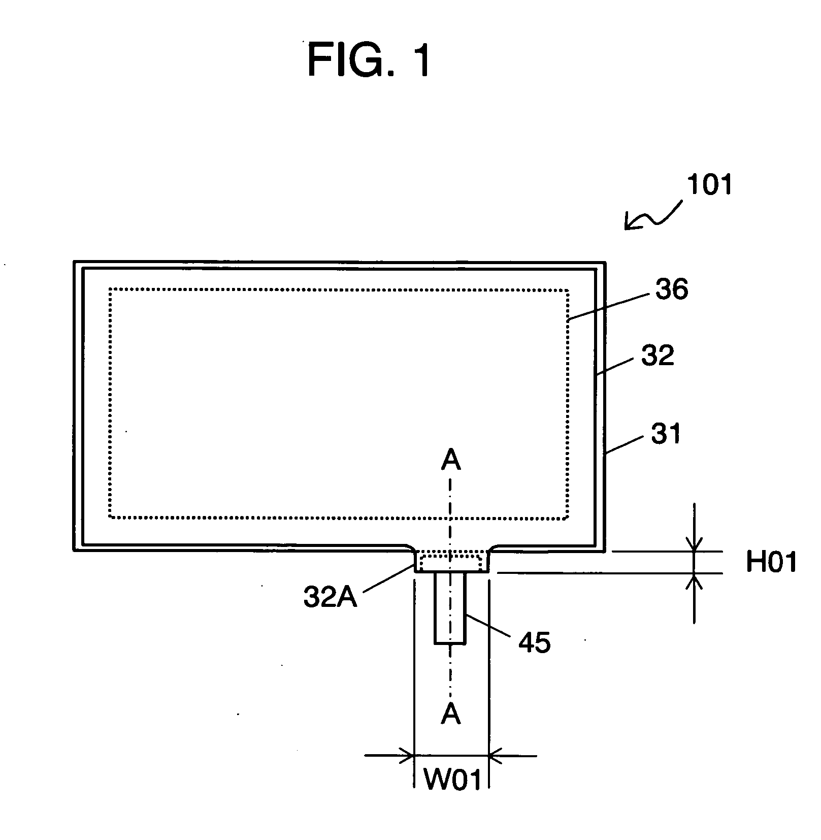
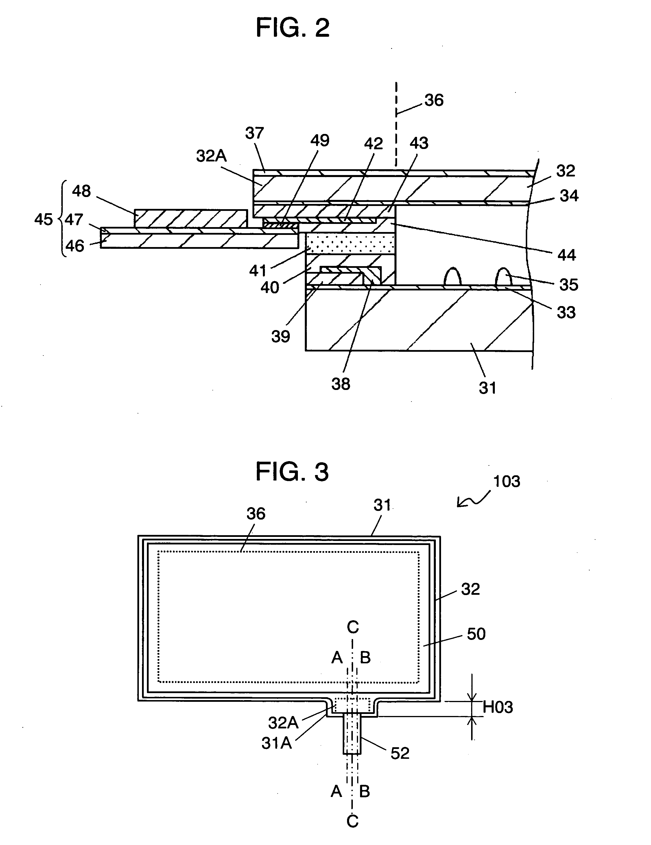
[0051]FIGS. 1 and 2 are views explaining touch panel 101 according to a first embodiment of the present invention.

[0052] Touch panel 101 comprises first transparent substrate 31 made of soda glass processed in an approximately rectangular shape, second transparent substrate 32 having flexibility made of a biaxially oriented polyethylene terephthalate film having a thickness of 188 μm on the operational side and flexible printed-circuit board (hereinafter, referred to also as “FPC”) 45.

[0053] First transparent electrically conductive film 33 made of indium tin oxide (hereinafter, referred to also as “ITO”) is formed on an entire top face of first transparent substrate 31 and, further, small dot spacers 35 formed from insulating epoxy resin or the like are disposed at specified intervals on first transparent electrically conductive film 33 inside visible area boundary 36 shown by a dotted line.

[0054] Second transparent substrate 32 comprises second transparent electrically conducti...

embodiment 2

[0091] FIGS. 3 to 5 are views explaining a touch panel according to Embodiment 2 of the present invention. Parts having same structures as those in Embodiment 1 are marked with same references and will not be described in detail.

[0092] Touch panel 103 according to Embodiment 2 includes first transparent substrate 31 on which first transparent electrically conductive film 33 is formed, second transparent substrate 32 on which second electrically conductive film 34 is formed and FPC 52.

[0093] Touch panel 103 according to Embodiment 2 has a structure such that first transparent substrate 31 and second transparent substrate 32 are both made of a polycarbonate film; and first transparent substrate 31 has projection portion 31A and second transparent substrate 32 has projection portion 32A. In order to obtain an optical isotropy, the polycarbonate film is produced by a casting method.

[0094] FPC 52 is a double-sided wiring type which has wiring patterns 53 and 54 on top and bottom faces...

embodiment 3

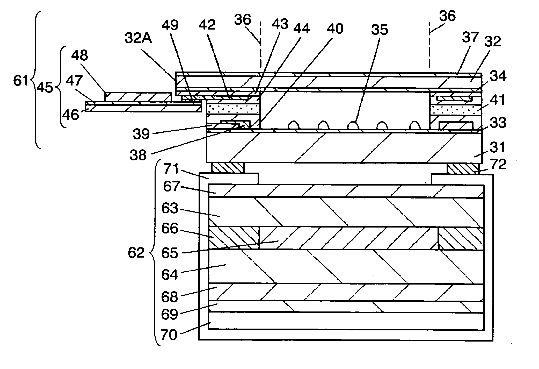
[0123] With reference to Embodiment 3, a liquid crystal display device attached with touch panel (hereinafter, referred to also as “TTP-LCD”) 106 in which touch panel 61 as described in Embodiment 1 is mounted on a liquid crystal display device is described below. Parts having same structures as those in Embodiment 1 are marked with same references and will not be described in detail.

[0124]FIGS. 6 and 7 are views explaining TTP-LCD 106 according to Embodiment 3 of the present invention, in which touch panel 61 is provided on a display screen of liquid crystal display device 62.

[0125] Liquid crystal display device 62 includes upper substrate 63, lower substrate 64, liquid crystal layer 65, seal layer 66, upper polarizing plate 67, lower polarizing plate 68, light guide plate 69, backlight 70, and case bezel 71.

[0126] In FIG. 6, other components involved in liquid crystal display device 62, for example, a circuit substrate for liquid crystal display drive or various types of semico...


PUM


Abstract

The touch panel has a structure such that a projection portion is provided on a second transparent substrate and a flexible printed-circuit board is bonded by thermocompression to the projection portion. By allowing width of a picture frame to be smaller in other portions than the projection portion, downsizing and a lighter weight of a touch panel-carrying apparatus can be attained. By bonding a sheet member such as a polarizing plate to a top face of the second transparent substrate excluding an area of the projection portion, stress to be applied from the sheet member to the thermocompression-bonding portion of the FPC is reduced and, therefore, electric connection stability of the FPC can be enhanced.

Description

TECHNICAL FIELD [0001] The present invention relates to a touch panel which is provided on the side of a display surface of a liquid crystal display apparatus or the like and can input a specified signal by pressing the surface corresponding to a displayed content with a pen or a finger, and also relates to a liquid crystal display apparatus provided with the touch panel. BACKGROUND OF THE INVENTION [0002] In recent years, in portable apparatuses or electronic apparatuses which require menu selections, the number of apparatuses which mount a touch panel and can input a specified signal corresponding to a displayed content by pressing with a pen or a finger is increasing. [0003] Among many types of touch panels, an analog-type touch panel comprising a resistive film which has been mainly used is explained with reference to Japanese Patent Laid-Open Application No. 2002-132449 using accompanying drawings. [0004] In order to facilitate understanding of a structure of the touch panel, t...

Claims


Application Information

Patent Timeline
IPC IPC(8): G02F1/1333G02F1/133G02F1/1335G06F3/03G06F3/041G06F3/045G06K11/06G09F9/00G09G5/00H01H9/02H01H13/70H01H13/712H05K3/36
CPCH05K3/361G06F3/0412G06F2203/04103G06F3/045G06F3/04164
Inventor NAKANISHI, AKIRAFUJII, SHIGEYUKI
Owner PANASONIC CORP
Why Eureka
Try Eureka