Medical guide wire

a technology of guide wires and wires, which is applied in the field of medical guide wires, can solve the problems of long replacement time of the appliance itself, difficult to handle the guide wire, complicated and troublesome manipulation, etc., and achieve the effect of shortening the length of the guide wire body itself, reducing manpower costs, and shortening the tim

Inactive Publication Date: 2005-05-12
OLYMPUS OPTICAL CO LTD
View PDF18 Cites 70 Cited by
  • Summary
  • Abstract
  • Description
  • Claims
  • Application Information

AI Technical Summary

Benefits of technology

[0022] According to the present invention, moreover, one end of the substantially wire-shaped retainer is coupled to the distal end portion side of the guide wire body, and the wire-shaped retainer extends parallel to the guide wire body and close to the hand-side end of the guide wire body on its proximal end portion side. In inserting or removing the appliance into the appliance passage channel of the endoscope through the guide wire body, therefore, the guide wire body can be fixed by holding the proximal end portion side of the wire-shaped retainer in a manner such that the distal end portion of the guide wire body projects for a given length from the channel of the endoscope. Since the appliance can be inserted or removed in this state, the length of the guide wire body itself can be made shorter, and the appliance can be replaced in a shorter time and more easily. Further, the manpower cost can be lowered since only one or no assistant is required by the operation for replacing the endoscopic appliance. Since the configuration on the appliance side need not be changed at all, moreover, the appliance replacement operation can be easily carried out without interfering with the conventional operating method or the sense of operation.
[0023] According to the present invention, there is provided a medical guide wire comprising a guide wire body to be passed through a channel of an endoscope, the guide wire body serving to guide an appliance to be inserted into the human body in insertion operation, the guide wire body being provided with an engagement aiding portion on the distal end portion side thereof, adapted releasably to engage a guide wire fixing mechanism on the side of a distal end opening of the channel of the endoscope, thereby aiding engagement with the guide wire fixing mechanism, when the distal end portion of the guide wire body is detachably anchored by means of the guide wire fixing mechanism.
[0024] According to the present invention, moreover, higher fixing strength can be obtained in a manner such that the engagement aiding portion on the distal end portion side of the guide wire body is caused releasably to engage the guide wire fixing mechanism on the distal end opening side of the channel of the endoscope, thereby aiding engagement with the guide wire fixing mechanism, when the distal end portion of the guide wire body is held and detachably anchored by means of the guide wire fixing mechanism.

Problems solved by technology

Thus, the manipulation is complicated and troublesome.
Since the guide wire e is as long as about 4,000 mm, moreover, it is hard to handle the guide wire e so as not to allow it to touch any dirty region, such as the floor in a narrow endoscope chamber.
Since the appliance cannot be replaced unless it is moved for a distance corresponding to the overall length of the guide wire e, furthermore, the replacement of the appliance itself takes a long time.
Accordingly, the operation for replacing the endoscopic appliance inevitably requires a lot of time.
Therefore, much manpower cost is required, which inevitably increase the financial burdens on hospitals and patients.
Accordingly, its manufacturing cost is inevitably higher than the conventional contrastradiography catheter.
Thus, the increase of the shaft diameter worsens the ease of insertion in the channel of the endoscope, which possibly lowers the operational efficiency.
Further, the condition of the patient also affects the way the appliances are used.
According to this prior art, however, the number of available appliances is inevitably limited, which leaves little choice for the operator.

Method used


Image

  • Medical guide wire
  • Medical guide wire
  • Medical guide wire

Examples


first embodiment

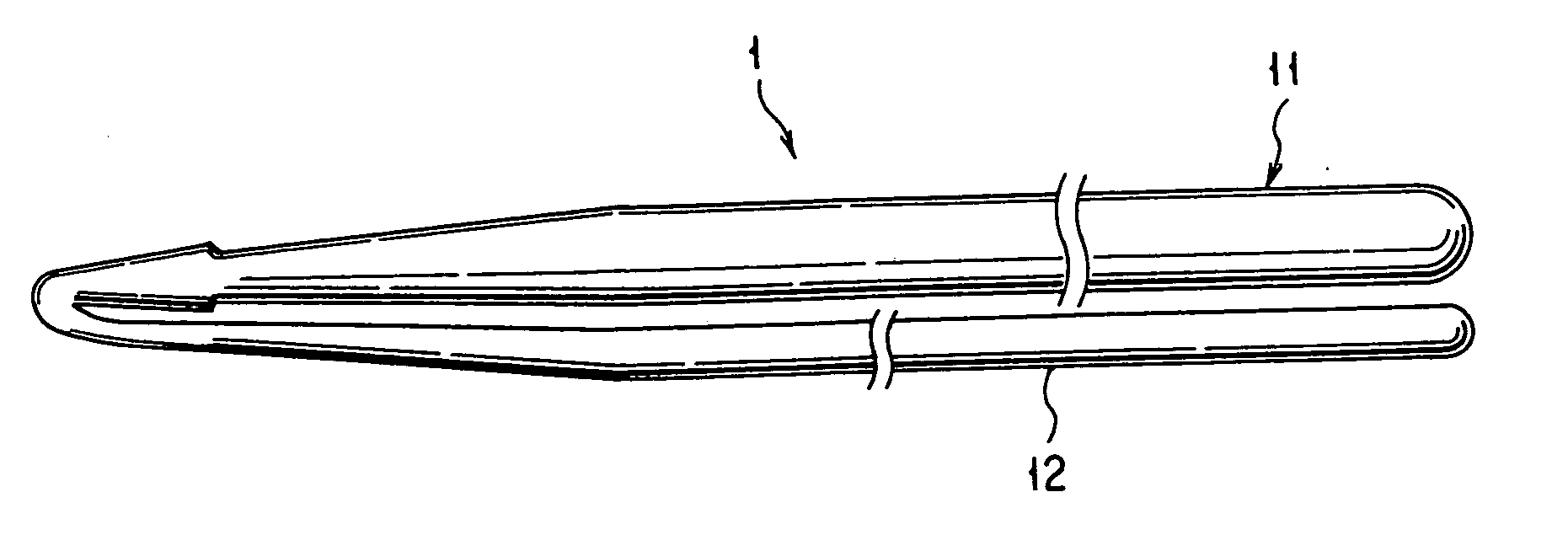
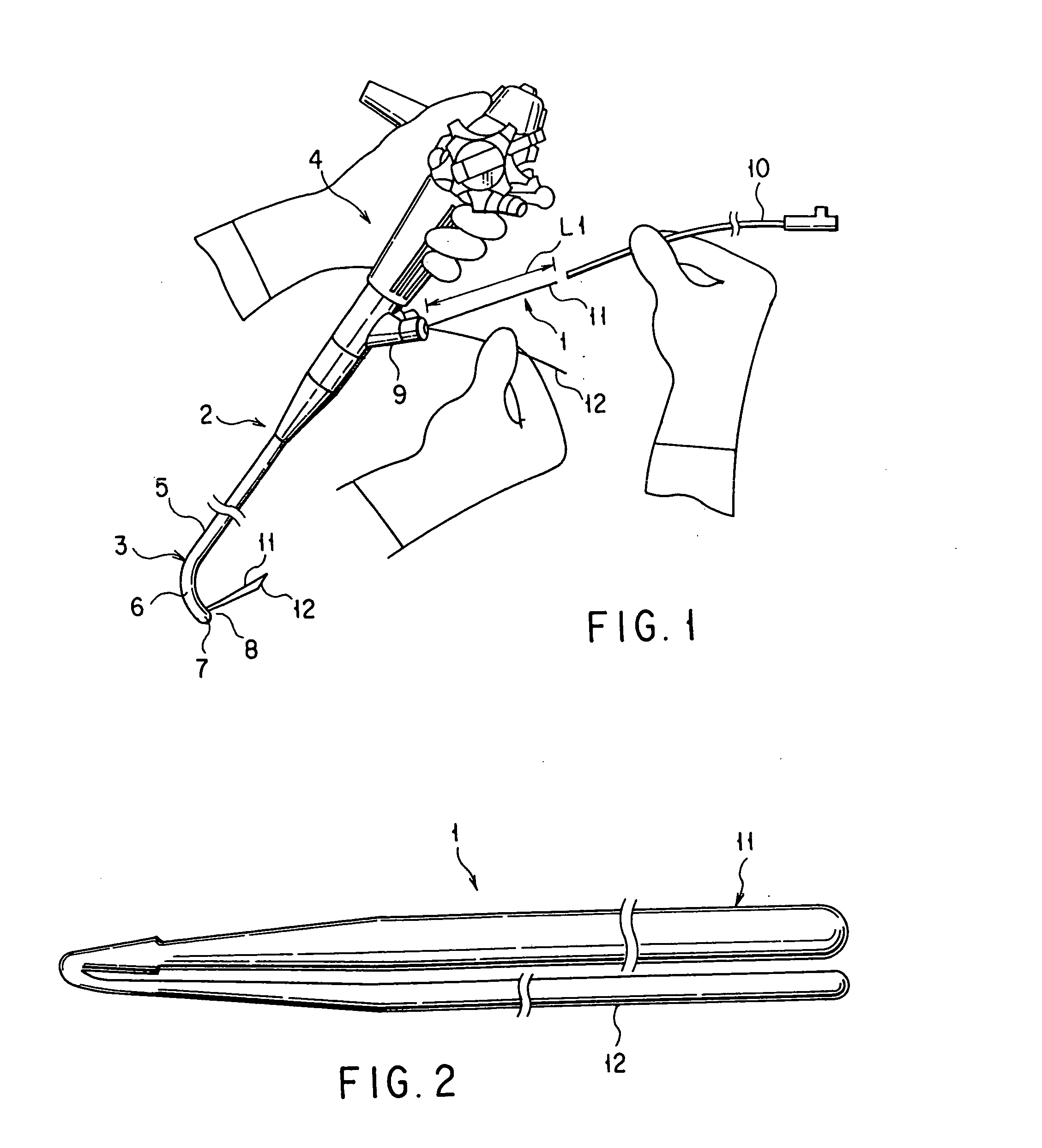
[0101] the present invention will now be described with reference to FIGS. 1 to 6. FIG. 1 shows a state in which a medical guide wire 1 of the present embodiment and an endoscope 2 are used in combination. The endoscope 2 is provided with an elongate insert section 3 to be inserted into the body cavity, a hand-side operating section 4 coupled to the proximal end portion of the insert section 3, and a universal cord (not shown) to which the proximal end portion of the operating section 4 is coupled. Further, the insert section 3 is provided with components that include an elongate flexible tube portion 5 having flexibility, a curved portion 6 coupled to the distal end of the flexible tube portion 5, and a distal end portion 7 located in the extreme end position of the insert section 3.

[0102] An appliance passage channel (not shown) for use as an appliance passage guide way is located in the insert section 3 of the endoscope 2. The distal end portion 7 of the insert section 3 is forme...

second embodiment

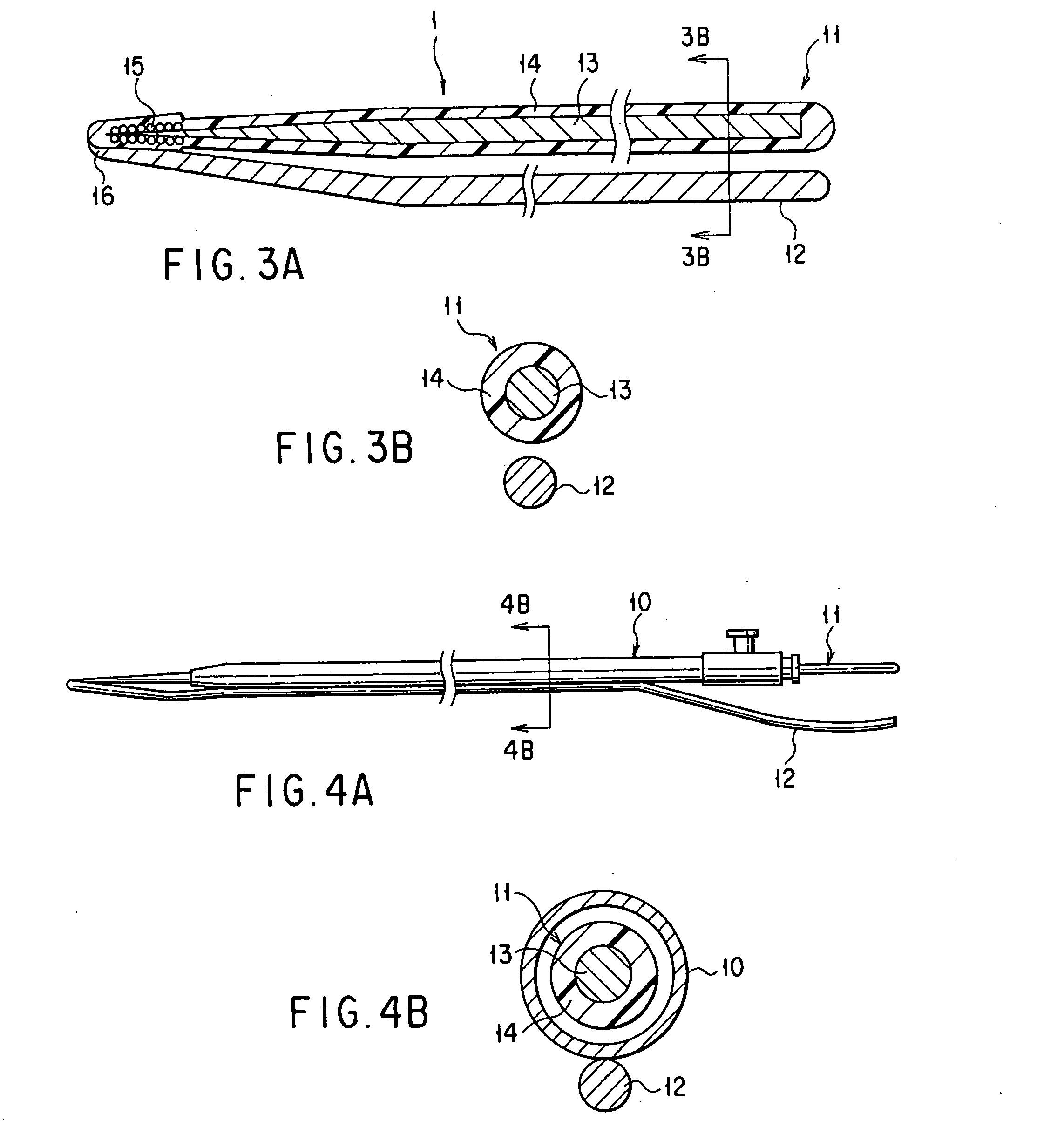
[0114]FIGS. 8A and 8B show the present invention. According to the present embodiment, the configuration of the medical guide wire 1 of the first embodiment (see FIGS. 1 to 6) is modified in the following manner.

[0115] More specifically, according to the present embodiment, an arcuate retaining wire 21 having a substantially crescent sectional shape is provided as the retaining wire 12 of the medical guide wire 1, as shown in FIG. 8A. As shown in FIG. 8B, the arcuate shape of the retaining wire 21 is adjusted to the arcuate shape of the outer peripheral surface of the catheter 10 or some other endoscopic appliance that is guided by means of a guide wire body 11.

[0116] In working the medical guide wire 1 of the present embodiment, an arcuate surface 21a of the retaining wire 21 is bonded and attached to an outer peripheral surface 10a of the catheter 10 or some other endoscopic appliance so as to extend along the arcuate shape of the surface 10a when the guide wire body 11 is insert...

fourth embodiment

[0121]FIG. 10 shows the present invention. According to the present embodiment, the configuration of the medical guide wire 1 of the first embodiment (see FIGS. 1 to 6) is modified in the following manner.

[0122] More specifically, according to the present embodiment, one wire 41 is doubled substantially in its central portion so that a guide wire body 11 and a retaining wire 12 are formed on its one fold portion 42 and other fold portion 43, respectively. An insulating coating layer 44 is provided around the whole wire 41 of the present embodiment.

[0123] In the configuration described above, the coating layer 44 of the insulator is provided around the whole wire 41 that constitutes the medical guide wire 1, so that the whole guide wire 1 can be insulated. As in the case of the third embodiment (see FIG. 9), therefore, the operator can be prevented from getting an electric shock or the like if he / she uses a high-frequency appliance, such as a papillotomy knife for excising a papilla...


PUM


Abstract

A fixing portion is provided so that the position of a guide wire (1) relative to an endoscope (2) is fixed lest it change by means of a retaining wire (12) that has one end coupled to the distal end portion side of a guide wire body (11) and the other end extending to the proximal end portion side of the guide wire body (11).

Description

TECHNICAL FIELD [0001] The present invention relates to a medical guide wire for guiding an appliance to be passed through a channel of an endoscope and inserted into the human body in insertion operation, in endoscopy or endoscopic operations on the pancreatic or biliary duct system, in particular. BACKGROUND ART [0002] Recently, there have been increasing endoscopic treatments in which diseases in the digestive tract system and pancreatic or biliary duct system are treated by means of an endoscope. Existing treatments on the pancreatic or biliary duct system using an endoscope include therapeutic treatments in which gallstones in the common bile duct, for example, are recovered by means of a balloon or holding forceps, as well as diagnostic treatments in which the biliary duct and pancreatic duct are visualized endoscopically. [0003] Usually, in performing an endoscopic treatment on the pancreatic, biliary, or hepatic duct by means of an endoscope, the distal end portion of the in...

Claims


Application Information

Patent Timeline
Patent Type & Authority Applications(United States)
IPC IPC(8): A61B1/00A61B1/018A61M25/01
CPCA61B1/00098A61B1/00137A61B1/018A61M2025/09183A61M25/09A61M2025/09125A61M2025/09175A61M25/01
Inventor ONUKI, YOSHIOKIMURA, KOH
Owner OLYMPUS OPTICAL CO LTD
Why Eureka
Try Eureka