Method for processing metal molding member having fine configuration, method for manufacturing metal molding member, extrusion die, method for manufacturing extruded member, and extruded member

Inactive Publication Date: 2005-05-19
SHOWA DENKO KK
View PDF3 Cites 1 Cited by
  • Summary
  • Abstract
  • Description
  • Claims
  • Application Information

AI Technical Summary

Benefits of technology

[0022] According to the third aspect of the present invention, a method for manufacturing an extrusion die comprises the step of extruding a billet through an extrusion die made by eliminating a molten residual layer formed on a surface of an electric-discharge machined portion by using a tool made by a wire discharge grinding method.
[0023] Accor

Problems solved by technology

Since these materials are rigid, the workability is poor.
Since high pressure will be applied to an extrusion die, if such a molten residual layer exists in the surface portion of the die, the micro cracks will act as starting points of destructions, resulting in a shortened die life.
Furthermore, even in cases where a surface treatment is performed, the treatment may cause the exfoliation of the surface treated layer, which in turn shortens the life of the surface treatment.
That is, in cases where an electric-discharge machined portion has a minute configuration including, for example, a slot of less than 0.3 mm width, the method cannot cope with such a minute configuration.
Furthermore, the strength of elimination processing varies from portion to portion and therefore a dull processed configuration will be generated, which deteriorates the processing dimensional accuracy.
Thus, the charact

Method used


Image

  • Method for processing metal molding member having fine configuration, method for manufacturing metal molding member, extrusion die, method for manufacturing extruded member, and extruded member
  • Method for processing metal molding member having fine configuration, method for manufacturing metal molding member, extrusion die, method for manufacturing extruded member, and extruded member
  • Method for processing metal molding member having fine configuration, method for manufacturing metal molding member, extrusion die, method for manufacturing extruded member, and extruded member

Examples


example 1

[0065] The following tests were performed in order to evaluate the effects of the embodiment.

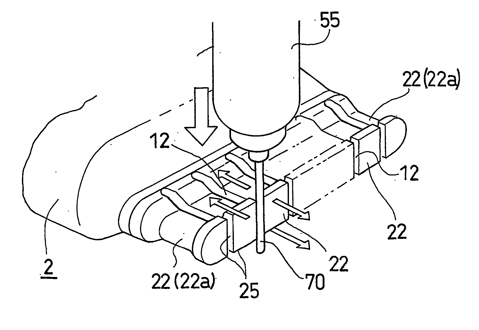
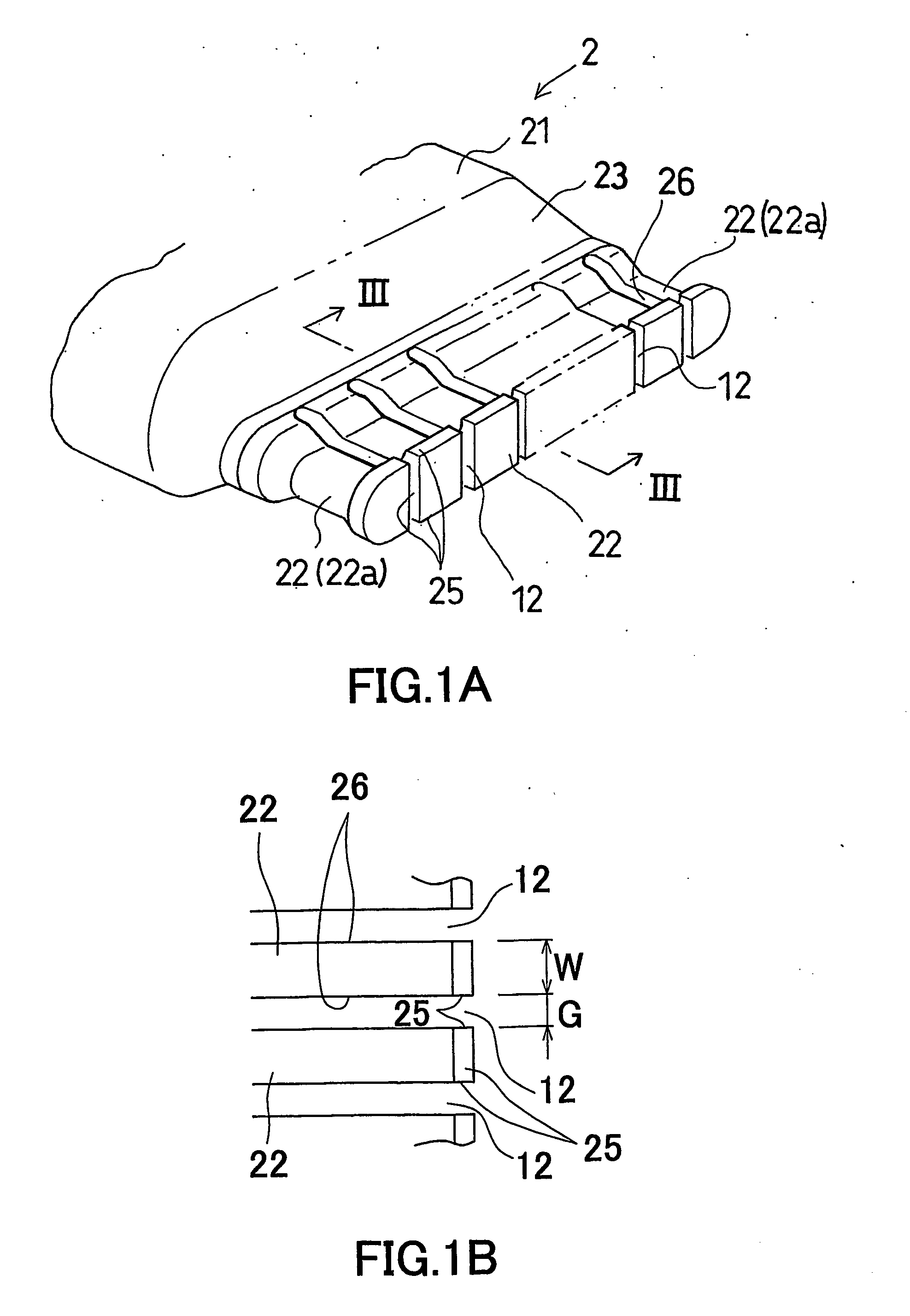
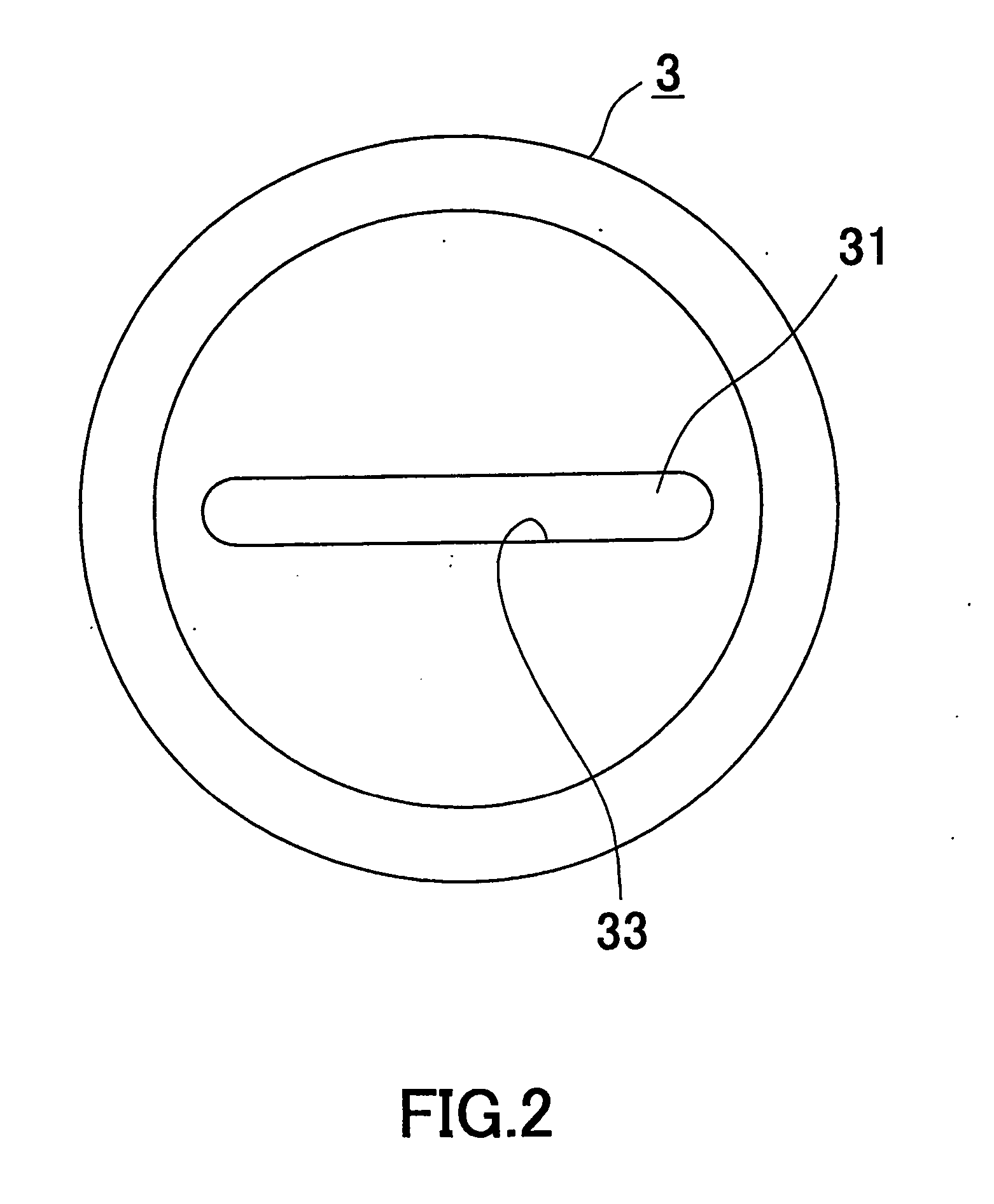
[0066] Four pieces of steel dies each equipped with the mandrel 2 having rectangular columnar portions 22 were prepared in order to extrude an aluminum tube 200 having rectangular hollow portions 202 arranged in the widthwise direction as shown in FIG. 8. The height of the bearing portion 25 of the columnar portion 22 was set to be 0.7 mm; the width thereof (see FIG. 1B) was set to be 0.4 mm; the width G of the groove 12 between the adjacent columnar portions 22 was set to be 0.1 mm; the length of the opening 31 of the female die 3 was set to be 16.0 mm; and the height (width) of the opening 31 was set to be 1 mm. The processing of the die was performed by electrical discharge machining.

[0067] As for one of the four dies, the molten residual layer of the electric-discharge machined surface including the inner surface 26 of the groove 12 was eliminated by a grinding method (with no abrasive...

example 2

[0073] The same types of dies 1 as in Example 1 were prepared. After the electric-discharge machining, the aforementioned eliminating processing for eliminating the molten residual layer of the processed surface were performed by changing the width G of the groove 12 between the adjacent columnar portions 22, respectively, in the state that the height of the bearing portion 25 of the columnar portion 22 is set to be 0.7 mm and the width W2 of the columnar portion 22 is set to be 0.4 mm. When one of the following problems was confirmed, it was regarded as the limitation of the elimination processing and the value was obtained. The problems include that the electric-discharge machined surface remains on the inner surface 26 of the groove 12 (when the eliminating of the molten residual layer becomes insufficient), that a dull beyond R0.05 is formed at the corner portion of the columnar portion 22, and that the breakage of the mandrel 2 (columnar portion 22) occurs during the eliminatio...


PUM

PropertyMeasurementUnit
Widthaaaaaaaaaa
Widthaaaaaaaaaa
Hardnessaaaaaaaaaa

Abstract

A molten residual layer formed on a surface 26 of an electric-discharge machined portion 12 of a metal molding member 1 is eliminated by using a tool 70 made by a wire discharge grinding method. According to the wire discharge grinding method, a minute tool which high in processing accuracy and high in hardness can be obtained. Since the molten residual layer formed on a surface 26 of the portion 12 due to the electric-discharge machining is eliminated by using the tool, the molten residual layer can be eliminated uniformly with high accuracy.

Description

[0001] Priority is claimed to Japanese Patent Application No. 2002-86296, filed on Mar. 26, 2002 and U.S. Provisional Patent Application No. 60 / 374,521, filed on Apr. 23, 2002, the disclosures of which are incorporated by reference in their entireties. CROSS REFERENCE TO RELATED APPLICATIONS [0002] This application is an application filed under 35 U.S.C. § 111(a) claiming the benefit pursuant to 35 U.S.C. § 119(e)(1) of the filing date of U.S. Provisional Application No. 60 / 374,521 filed on Apr. 23, 2002 pursuant to 35 U.S.C. § 111(b).TECHNICAL FIELD [0003] The present invention relates to a method for processing a metal molding member having a minute configuration, a method for manufacturing a metal molding member, an extrusion die, a method for manufacturing an extruded member and an extruded member. BACKGROUND ART [0004] In general, as a material of a metal molding member such as an extrusion die, a material excellent in abrasion resistance such as forged die steel or cemented ca...

Claims


Application Information

Patent Timeline
IPC IPC(8): B21C25/00B21C25/02B21C25/10B23H1/00B23H1/04B23H7/26B23H9/00B23H9/02B23P15/24
CPCB23H1/04B23H7/265B23H9/00B23H9/02B23P15/24Y10T29/45B21C25/02B21C25/10B23H1/00Y10T29/4544Y10T29/4506B21C25/00
Inventor HIRAMOTO, KIMIHISAHAMANO, HIDEMITSU
Owner SHOWA DENKO KK
Why Eureka
Try Eureka