Sputtering Target and Process for Producing Same

Active Publication Date: 2011-07-07
JX NIPPON MINING& METALS CORP
View PDF26 Cites 18 Cited by
  • Summary
  • Abstract
  • Description
  • Claims
  • Application Information

AI Technical Summary

Benefits of technology

[0018]The present invention forms a highly ductile and conductive metal coating layer on the outermost layer of a target in which oxides, carbides, nitrides, borides, intermetallic compounds, carbonitrides, and other substances without ductility exist in a matrix phase made of a highly ductile substance at a volume ratio of 1 to 50%, and is thereby able to obtain a target with superior surface characteristics. This metal coating layer yields the effect of being able to supplement the bond

Problems solved by technology

The generation of such defects in this sputtering is not only attributable to the sputtering method, but is also often caused by the target itself.
As such a cause of the generation of defects resulting from the target, there is the generation of particles and nodules.
Further, since such particles often adhere as a large cluster, for instance, these particles will cause a short circuit in the fine wiring film of electronic components, and lead to the generation of defective products.
Further, generally, the target face material is not reduced (eroded) evenly due to the sputtering, but there is a tendency that a specific area, a ring shape for example, is eroded depending on the inherent characteristics of the constituent material and sputtering device, and on method of applying voltage.
Never

Method used


Image

  • Sputtering Target and Process for Producing Same
  • Sputtering Target and Process for Producing Same

Examples


example 1

[0044]Co powder, Cr powder, Pt powder, and SiO2 powder were used as the raw material, and a target raw material was obtained based on the production conditions of hot pressing and HIP. The volume ratio of SiO2 without ductility in this target was 25%, and the average grain size of the SiO2 grains was 2 μm. The major component of the matrix phase was a uniform Co—Cr—Pt alloy.

[0045]After performing primary processing of cutting using a lathe to finalize a target shape, grinding processing was additionally performed, and the processes of wet secondary polishing including wet primary polishing based on pure water drop→alumina polishing agent drop were performed to adjust the surface and obtain a target.

[0046]The average surface roughness of the target in which the surface roughness was adjusted as described above; specifically, the measurement results of the center-line average surface roughness Ra, the ten-point average roughness Rz, the distance between local peaks (roughness motif) A...

example 2

[0052]Other than achieving Ra of 0.256 μm, Rz of 1.234 μm, AR of 118.76 μm, and AW of 1530.50 μm in the processes of wet secondary polishing, a cobalt coated target was produced based on the same production conditions as Example 1, and a sputtered film was formed on a substrate in an Ar 1.5 Pa atmosphere under the DC sputtering condition of 30 w / cm2.

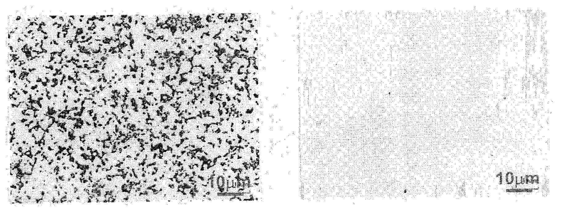
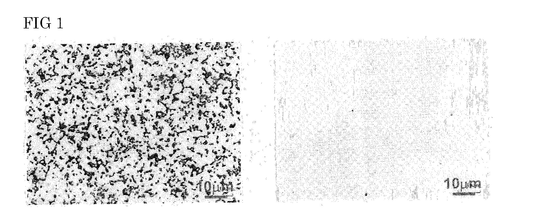
[0053]When observing the particles that were generated during the sputtering, the size of the particles was approximately 1 μm×1 μm (“long diameter×short diameter”; hereinafter the same), and there was hardly any difference in comparison to the grain size of oxides of approximately 1 μm×1 μm.

[0054]The results are similarly shown in Table 1. In addition, the number of defectives (defectives / mm2) caused by the particles was reduced to 2.2.

[0055]Even if the renter-line average surface roughness Ra is outside the range of 0.1 μm or less, the ten-point average roughness Rz is outside the range of 0.4 μm or less, distance between local peaks (...


PUM

PropertyMeasurementUnit
Lengthaaaaaaaaaa
Lengthaaaaaaaaaa
Lengthaaaaaaaaaa

Abstract

A sputtering target with low generation of particles in which oxides, carbides, nitrides, borides, intermetallic compounds, carbonitrides, and other substances without ductility exist in a matrix phase made of a highly ductile substance at a volume ratio of 1 to 50%, wherein a highly ductile and conductive metal coating layer is formed on an outermost surface of the target. Provided are a sputtering target capable of improving the target surface in which numerous substances without ductility exist and preventing or inhibiting the generation of nodules and particles during sputtering, and a method of producing such a sputtering

Description

TECHNICAL FIELD[0001]The present invention relates to a sputtering target with low generation of sparticles and to process for producing same.BACKGROUND ART[0002]The sputtering method is a well-known technique as a means for forming a thin film. The basic principle thereof is to apply voltage between a substrate (anode side) to which the thin film is to be formed and a target (cathode side) facing the substrate at a close distance and which is formed from a thin film forming substance, so as to change argon gas into a plasma. As a result, the argon ions generated thereby collide with the target, which is a cathode material, the energy thereof discharges (knocks out) the target material outside, and the discharged material is laminated on the opposed substrate face.[0003]A thin film forming device employing this sputtering principle includes various modified types such as a bipolar bias sputtering device, high frequency sputtering device, plasma sputtering device, but these devices e...

Claims


Application Information

Patent Timeline
IPC IPC(8): C23C14/34C25D5/00C25D7/00B05D5/12C23C16/06B05D3/00C23C16/44
CPCC23C14/3414
Inventor NAKAMURA, YUICHIROHISANO, AKIRASEKIGUCHI, JUNNOSUKE
Owner JX NIPPON MINING& METALS CORP
Why Eureka
Try Eureka