
Electromagnetic tracking system and method using a three-coil wireless transmitter

a wireless transmitter and electromagnetic tracking technology, applied in direction finders using radio waves, instruments, applications, etc., can solve the problems of inability to use medical imaging systems for instrument medical imaging systems are too slow to produce useable real-time images for instrument tracking in medical procedures, and the use of medical imaging systems for instrument tracking may be limited

Active Publication Date: 2005-05-19
NORTHERN DIGITAL
View PDF52 Cites 30 Cited by
  • Summary
  • Abstract
  • Description
  • Claims
  • Application Information

AI Technical Summary

Benefits of technology

[0022] Certain embodiments include an improved wireless electromagnetic tracking system. The tracking system includes a wireless transmitter coil trio attached to an object and transmitting a signal. The system also includes a receiver assembly with at least two receiver coil trios. The system further includes a tracker electronics for determining positioning information for the wireless coil based on the wireless coil and the two or more

Problems solved by technology

However, medical practitioners often do not have the use of medical imaging systems when performing medical procedures.
Typically, medical imaging systems are too slow to produce useable real-time images for instrument tracking in medical procedures.
The use of medical imaging systems for instrument tracking may be also limited for health and safety reasons (e.g., radiation dosage concerns), financial limitations, physical space restrictions, and other concerns, for example.
That is, a tracking system may be used in other settings where the position of an instrument in an object or an environment is unable to be accurately determined by visual inspection.
Tracking systems used to track larger objects, such as airplanes in relation to an airport, involve less accurate measurements than system that track smaller objects, such as surgical instruments.
Thus, the range of motion of the object being tracked is limited.

Method used


Image

  • Electromagnetic tracking system and method using a three-coil wireless transmitter
  • Electromagnetic tracking system and method using a three-coil wireless transmitter
  • Electromagnetic tracking system and method using a three-coil wireless transmitter

Examples


Embodiment Construction

[0030] For the purpose of illustration only, the following detailed description references a certain embodiment of an electromagnetic tracking system used with an image-guided surgery system. It is understood that the present invention may be used with other imaging systems and other applications.

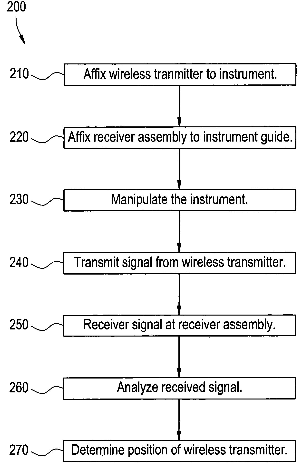
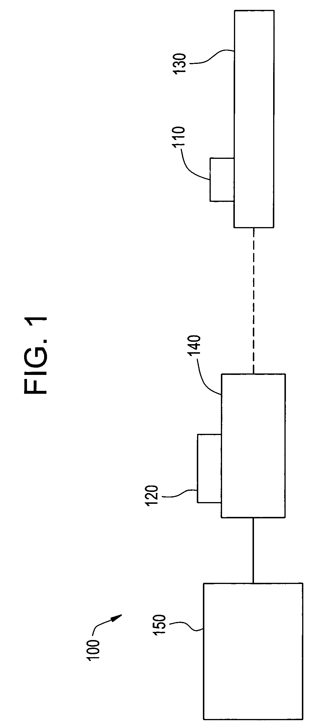
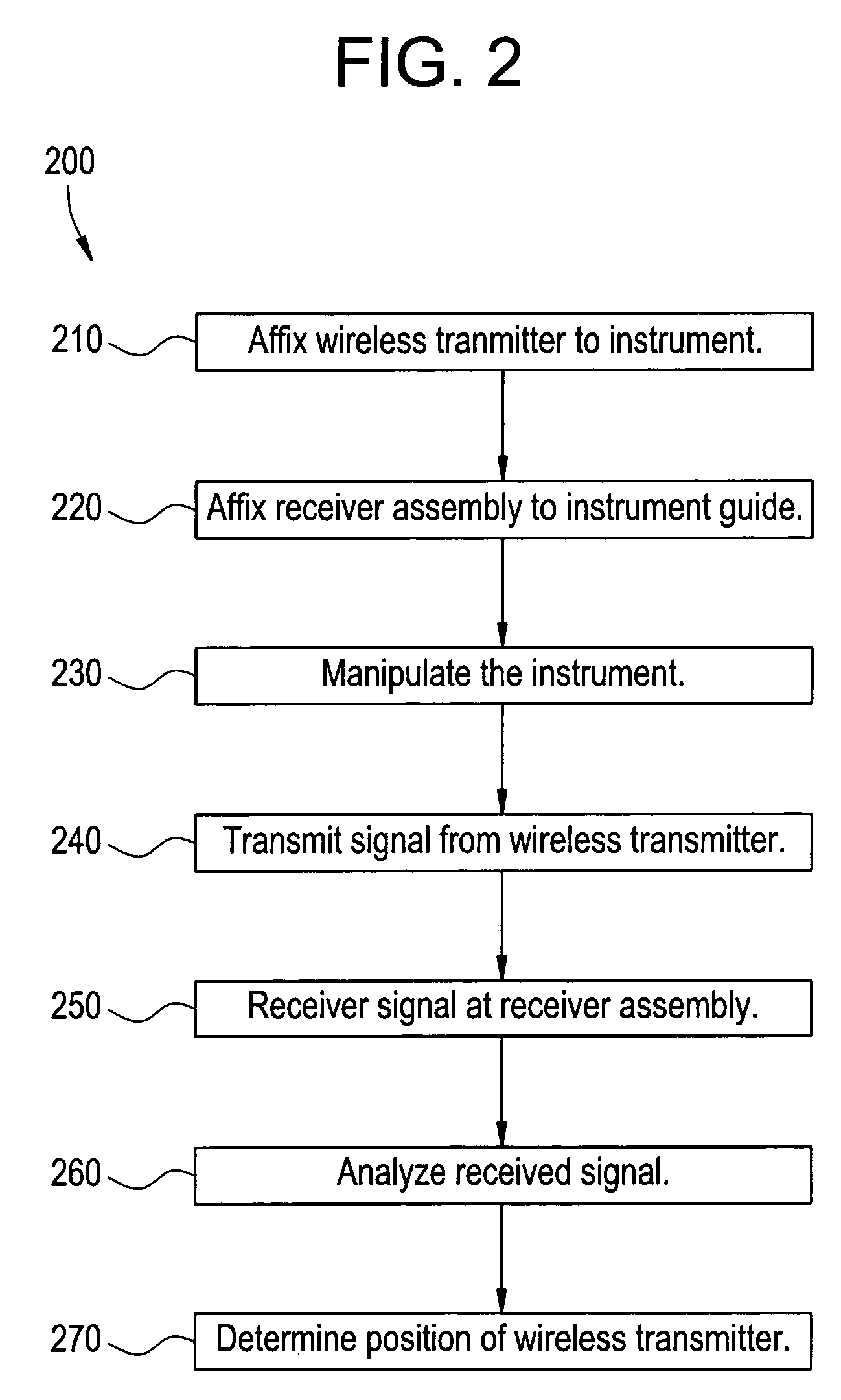
[0031]FIG. 1 illustrates an electromagnetic tracking system 100 used in accordance with an embodiment of the present invention. The tracking system 100 includes a wireless transmitter 110, a receiver assembly 120, an instrument 130, an instrument guide 140, and a tracker electronics 150. In an embodiment, the wireless transmitter 110 is positioned on the instrument 130. The receiver assembly 120 is located remotely from the instrument 130 and the transmitter 110. The instrument guide 140 is used to control the instrument 130.

[0032] In an embodiment, the tracker electronics 150 includes a Lucas 4650 processor. The tracker electronics 150 may be integrated with the receiver assembly 120 or ...


PUM


Abstract

Certain embodiments of the present invention provide a system and method for electromagnetic tracking using a three-coil wireless transmitter. The electromagnetic tracking system includes an instrument manipulated by a user to perform a task, a wireless transmitter for broadcasting a wireless signal, a receiver assembly for receiving the wireless signal, and electronics for determining positioning information for the instrument based on a relationship between the receiver assembly and the wireless transmitter. In an embodiment, the wireless transmitter includes a wireless transmitter coil trio. In an embodiment, the receiver assembly includes two receiver coil trios.

Description

[0001] RELATED APPLICATIONS [0002] The present application relates to, and claims priority from, U.S. Provisional Application No. 60 / 520,189 filed on Nov. 14, 2003, and entitled “Electromagnetic Tracking System and Method Using a Three-Coil Wireless Transmitter” (Attorney Docket Number 130396NV).FEDERALLY SPONSORED RESEARCH OR DEVELOPMENT [0003] [Not Applicable]MICROFICHE / COPYRIGHT REFERENCE [0004] [Not Applicable]BACKGROUND OF THE INVENTION [0005] The present invention generally relates to an electromagnetic tracking system. In particular, the present invention relates to an electromagnetic tracking system using a wireless transmitter. [0006] Many medical procedures involve a medical instrument, such as a drill, a catheter, scalpel, scope, stent or other tool. In some cases, a medical imaging or video system may be used to provide positioning information for the instrument, as well as visualization of an interior of a patient. However, medical practitioners often do not have the us...

Claims


Application Information

Patent Timeline
IPC IPC(8): A61B5/06A61B17/00A61B17/16A61B17/17A61B19/00G01V15/00
CPCA61B5/06A61B17/16A61B17/1707A61B19/52A61B19/5244G01V15/00A61B2019/5251A61B2019/5458A61B2019/547A61B2019/5475A61B2017/00734A61B90/36A61B2090/3975A61B34/20A61B2034/2051A61B2090/3958A61B2090/397A61B5/062G01B7/004
Inventor ANDERSON, PETER TRANEUS
Owner NORTHERN DIGITAL
Learn More