
Atraumatic high-retention headpiece

a headpiece and high-retention technology, applied in electrotherapy, therapy, etc., can solve the problems of skin irritation and/or tissue damage, irritation, soreness, redness, etc., to improve comfort and blood flow, and distribute headpiece forces evenly

Active Publication Date: 2011-09-27
ADVANCED BIONICS AG
View PDF36 Cites 77 Cited by
  • Summary
  • Abstract
  • Description
  • Claims
  • Application Information

AI Technical Summary

Benefits of technology

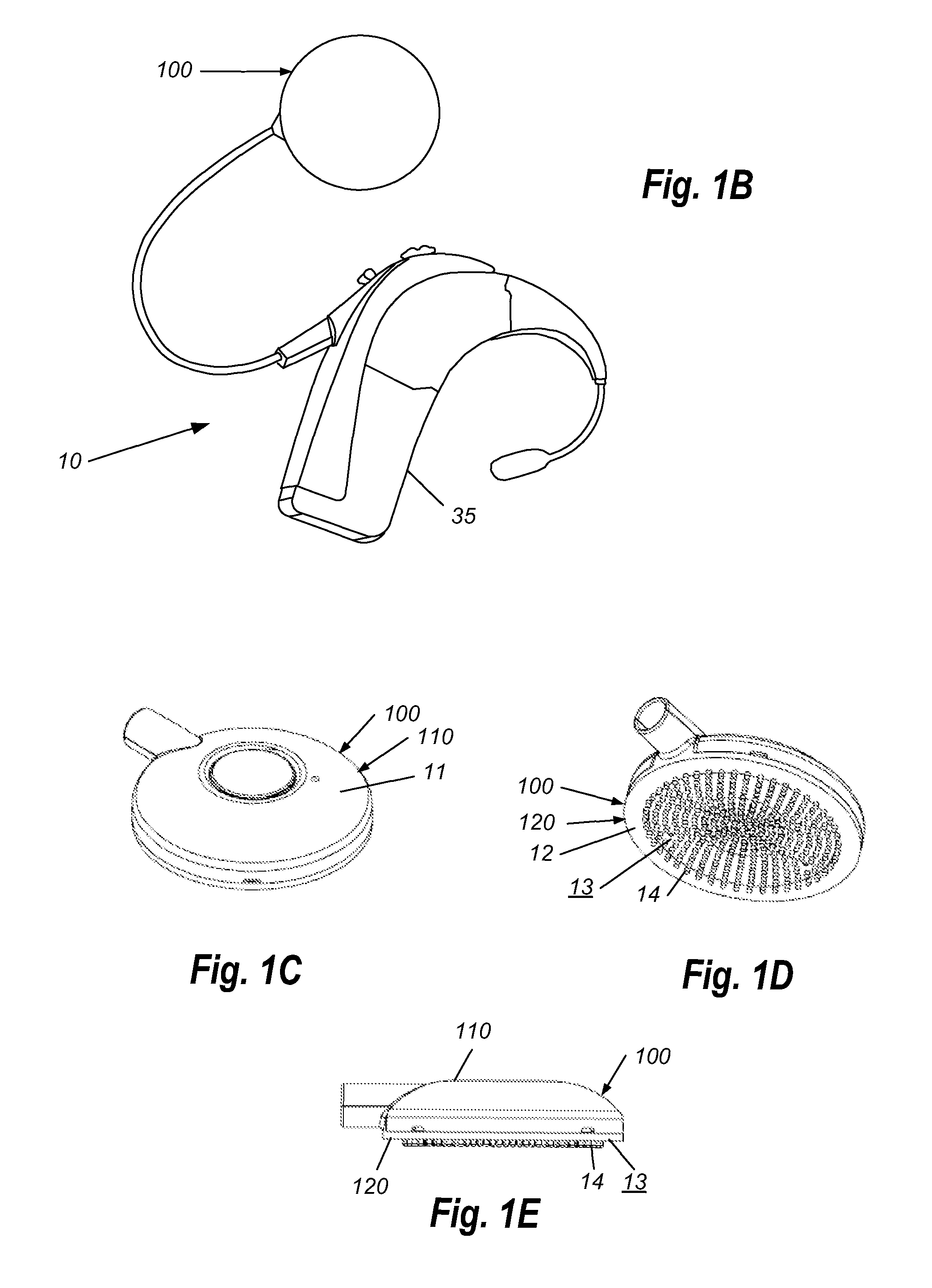
[0008]The present invention solves the above and other needs by providing a magnet- and coil-containing headpiece with bottom surface having a plurality of flexible bumps that define multiple low- and zero-pressure channels. This allows blood to flow in nearly every part of the skin and tissue underneath the headpiece. Because the bumps can resiliently deform and flex independently, the headpiece conforms to the contour of the skin, thus more evenly distributing headpiece forces over a larger skin area, further improving comfort and blood flow. Additionally, the resiliency of the bumps allows for the headpiece to dynamically conform to the skin with minor changes of the skin. Such changes can occur as the surgical wound heals, with swelling that can last one or two months following surgery. Changes to skin flap thickness can also occur with pregnancy, water retention, weight gain or loss, age, hair growth, and movement with chewing or talking. This ability to conform to the contour of the skin allows the headpiece to adjust naturally to small changes, being relatively insensitive to magnet strength, such that the magnet strength does not need to be adjusted as often by adding, subtracting, or replacing magnets in the headpiece. While major changes may require such adjustment, minor changes will be accommodated by the flexible bumps.
[0009]The bump configuration, shape, surface finish, and material can be used to provide a high-friction interface to reduce movement of the headpiece under lateral loading, thereby improving retention of the headpiece.
[0010]In some embodiments of the invention, a rigid bottom surface may be used to provide support for the bumps, allowing use of the softest possible materials for the bumps themselves, further improving comfort and reducing pressure without compromising retention.

Problems solved by technology

However, a known problem is that the pressure of the headpiece against the skin may cause skin irritation and / or tissue damage due to blood flow restriction.
The issue is further compounded by variable skin curvatures resulting, in part, from the shape of the implanted device and variable skin thicknesses among patients.
Because of this, force may be applied over a small area of the skin flap, resulting in very high local pressures, which can lead to irritation, soreness, redness, and even necrosis of the skin flap tissue or extrusion of the implanted device.
Reducing magnetic forces to address the pressure issues has the undesirable effect of poor headpiece retention.

Method used


Image

  • Atraumatic high-retention headpiece
  • Atraumatic high-retention headpiece
  • Atraumatic high-retention headpiece

Examples


Embodiment Construction

[0028]The following description of the presently contemplated best mode of practicing the invention is not to be taken in a limiting sense, but is made merely for the purpose of describing the general principles of the invention. The scope of the invention should be determined with reference to the claims.

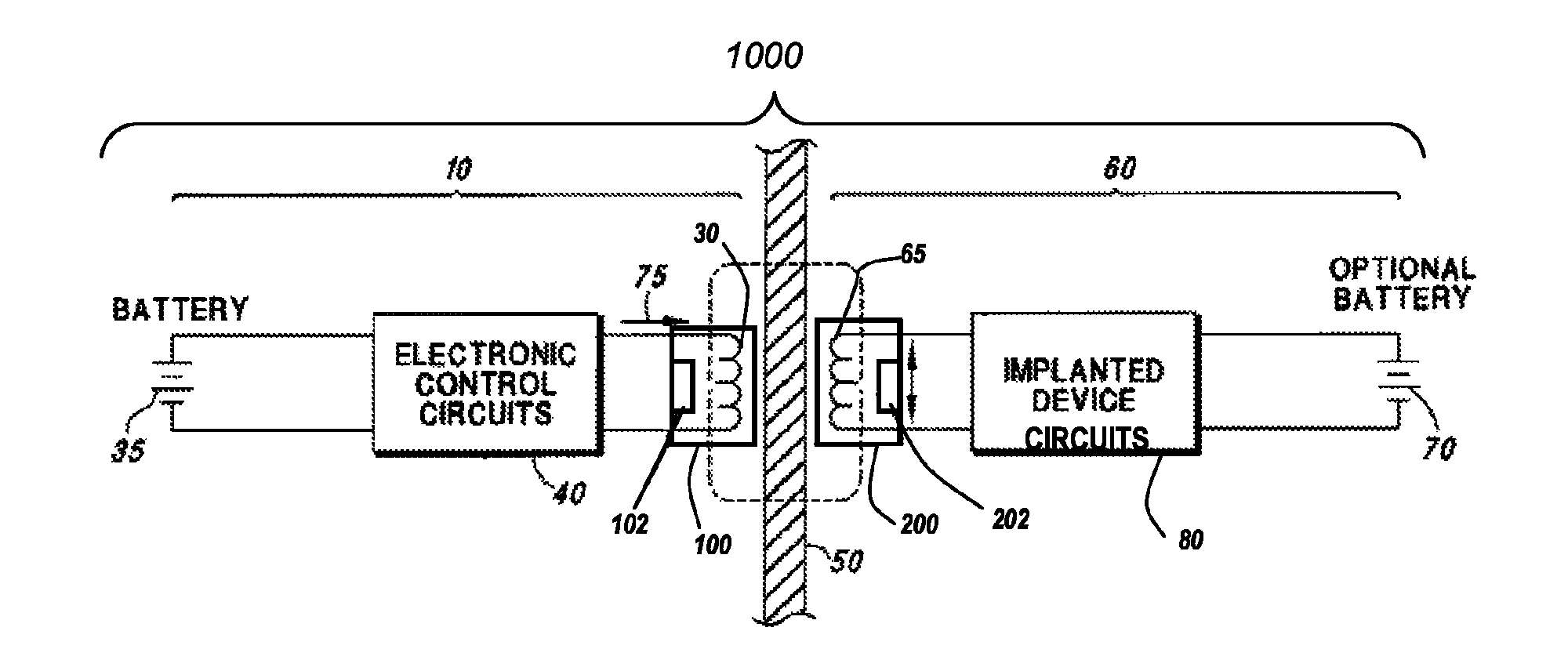
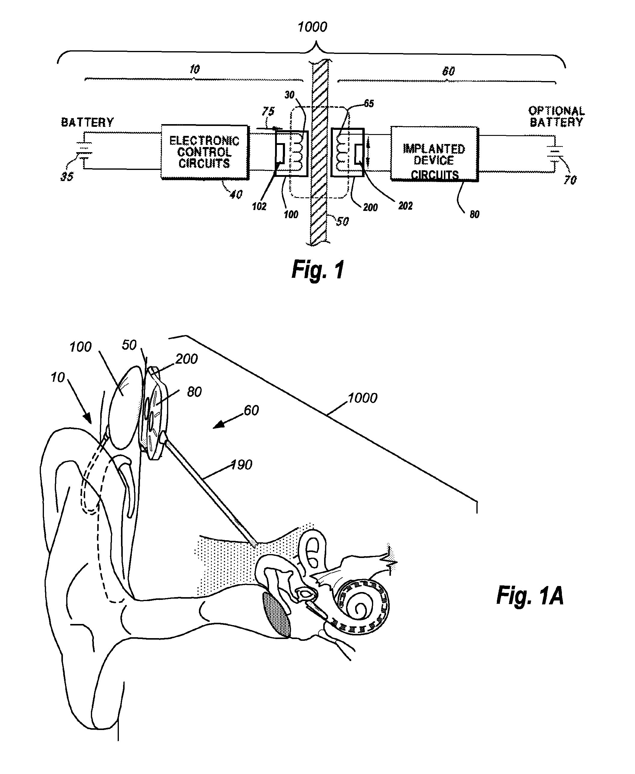
[0029]Referring first to FIGS. 1 and 1A, there are shown a schematic diagram and perspective illustration of a cochlear implant system 1000 having external componentry 10 and implanted componentry 60. The implanted componentry 60 may comprise a single implanted device or may comprise two or more separate devices that can be detachably attached to each other; for example, a lead may be permanently integrated with an implantable cochlear stimulator (ICS), or a battery may be sealed within the housing of the ICS, or the lead and / or battery may be detachably attachable to the ICS, or the ICS may otherwise be modular. As used herein, the terms “implanted device” and “cochlear implant” r...


PUM


Abstract

A headpiece for a cochlear implant system includes a transcutaneous transmission coil that transfers power and / or data to an implantable device implanted under a user's skin. The headpiece includes a magnet for holding the transmission coil in close proximity to the receiver coil in the implanted device, which also contains a magnet, and provides the desired alignment between the coils so that inductive coupling may efficiently occur. The headpiece has a bottom surface for skin contact that includes a plurality of flexible bumps configured to distribute pressure over a large surface area while allowing blood flow throughout the area. This also provides friction contact with the skin to help secure the headpiece, reducing movement due to lateral loading, while reducing skin irritation and erosion.

Description

RELATED APPLICATIONS[0001]The present application claims the benefit under 35 U.S.C. §119(e) to U.S. Provisional Patent Application No. 61 / 041,338, filed on Apr. 1, 2008, which is herein incorporated by reference in its entirety.BACKGROUND OF INVENTION[0002]The present invention relates to the transfer of electromagnetic energy between coils, and more particularly, to an external device secured to the skin of a patient, having a coil for transmitting power and / or data to an implanted device and / or to a replenishable power source associated with the implanted device.[0003]The present invention will be described in the context of a cochlear implant system; however, it should be understood that it is also useful for other medical devices such as neuromuscular stimulators, implantable pumps, and other implantable devices that are designed to be surgically inserted within a patient's body to carry out a medically related function for an extended period of time. Indeed, the present invent...

Claims


Application Information

Patent Timeline
Patent Type & Authority Patents(United States)
IPC IPC(8): A61N1/00
CPCA61N1/36032A61N1/37229A61N1/3787A61N1/36038
Inventor TZIVISKOS, GEORGEBROWNEN, MICHAEL D.ORINSKI, WILLIAM G.
Owner ADVANCED BIONICS AG
Learn More