Raman amplifier, pump source for use in a raman amplifier and method for amplifying an optical signal

a technology of amplifier and optical pump, which is applied in the direction of optics, electromagnetic repeaters, instruments, etc., can solve the problems of power penalty, power penalty, and the benefit of increasing the signal power beyond a predetermined amount, and achieve the extra optical power required

Active Publication Date: 2005-05-19
MOLEX INC
View PDF39 Cites 16 Cited by
  • Summary
  • Abstract
  • Description
  • Claims
  • Application Information

AI Technical Summary

Benefits of technology

[0017] One object of the present invention is to more accurately determine whether the conventional design approach for providing no SBS in a co-pumped (or forward pumped) Raman system, is a sound criteria by which to configure such a system.

Problems solved by technology

However, the benefit of increasing the signal power beyond a predetermined amount can be wasted (i.e., a power penalty) due to the non-linear effect of the optical fiber itself.
In other words, for a given BER, the power penalty is the extra optical power required to produce the same BER than if there was no noise or interference added by the non-linear effect.
However, the industry has generally failed to adopt forward pumped Raman amplifiers because of several problems.
First, additional noise is present due to the transfer of pump relative intensity noise (RIN) to the signal light.
However, low RIN pump lasers were later found to cause a new problem of causing stimulated Brillouin scattering (SBS) of pump light when used in a Raman amplifier system.
Consequently, pump RIN degrades (i.e., the amount of noise is increased) in the fiber when the pump causes SBS.
Furthermore, the presence of SBS especially at large levels means that some of the pump power is lost wasted, which leads to lower amplifier efficiency.
According to these limitations with forward pump systems, conventional design philosophy dictates that no pump SBS can be tolerated for use in an optical communication system.
Once again, because the conventional design practice is to set to zero SBS, low RIN pump LDs are not able to be used at their full power capacity, thus making low RIN LDs less effective than if SBS was deemed not to be a problem at all.
Moreover, the present inventors recognized that by not appreciating the source of the exact relationship between RIN and SBS, it would not be possible to select pump LDs for a forward pumped or co-pump Raman amplifier and still provide maximum system performance, or make full use of the LD's pump power capacity.
Since LD modules are expensive, the cost of each “acceptable” part increases as the manufacturing yield decreases.
Likewise, more LDs are deemed unacceptable when they produce a higher PRR than the selection criteria.

Method used


Image

  • Raman amplifier, pump source for use in a raman amplifier and method for amplifying an optical signal
  • Raman amplifier, pump source for use in a raman amplifier and method for amplifying an optical signal
  • Raman amplifier, pump source for use in a raman amplifier and method for amplifying an optical signal

Examples


Embodiment Construction

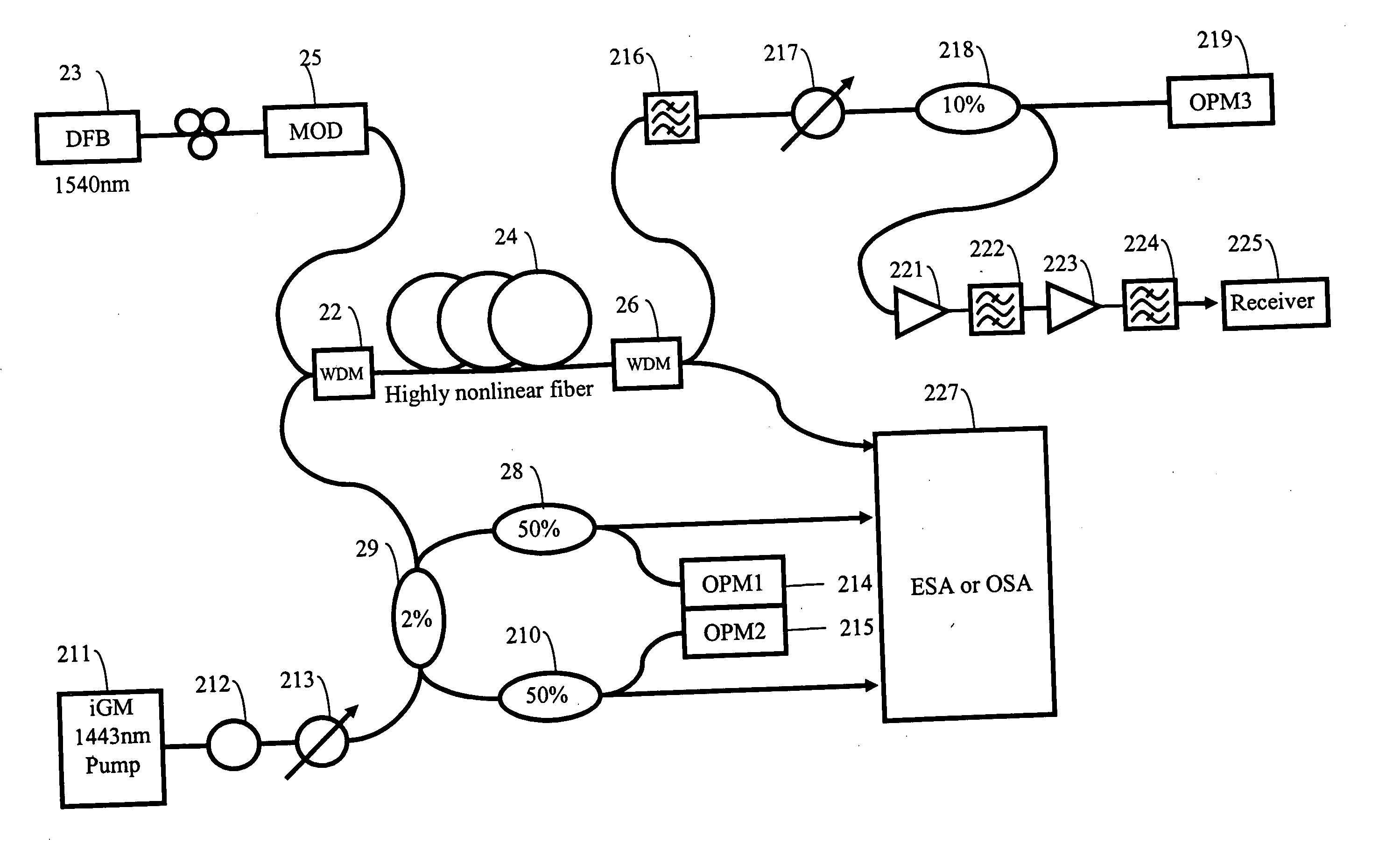
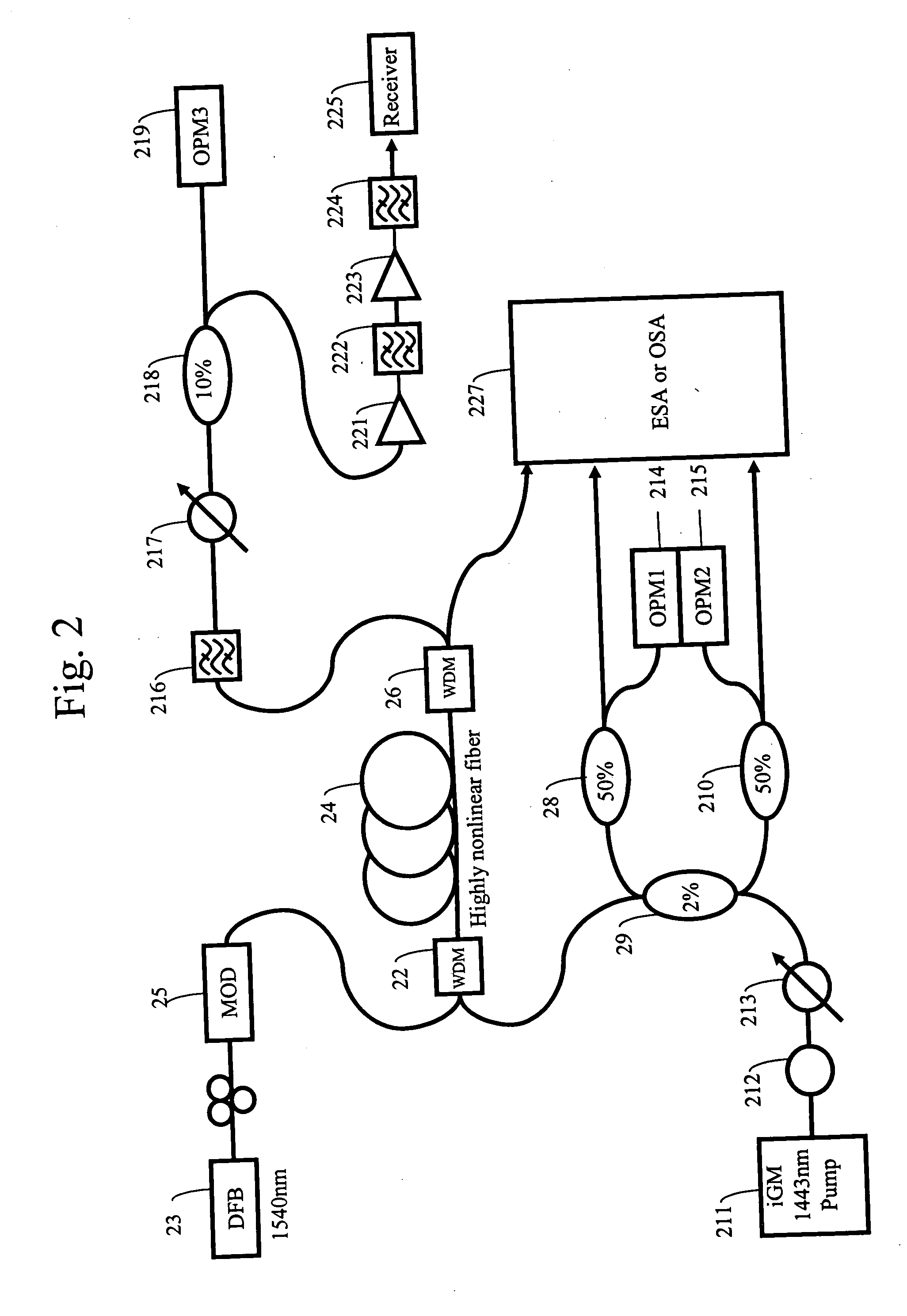
[0039] Referring now to the drawings, FIG. 2 illustrates a block diagram of a measurement setup that may be used according to the present invention for selecting suitable pumps and accurately determining SBS levels. A pump source 211 is a 1443 nm iGM (inner-grating stabilized multimode pump laser) such as that described in U.S. Pat. No. 6,614,823 entitled “Semiconductor Laser Device Having a Diffraction Grating on a Light Reflection Side”, the entire contents of which being incorporated herein by reference. The iGM laser is a low RIN pump laser with a built-in isolator. The output of the pump 211 is provided to an external depolarizer 212 made of 10 meters of polarization maintaining fiber. The output of the external depolarizer 212 is provided to a variable optical attenuator 213 that is used for changing (manually or under computer control) an input power to the amplifier fiber 24 (which in this case is a highly non-linear fiber) under constant pump output power so as to keep the ...


PUM

PropertyMeasurementUnit
lengthaaaaaaaaaa
lengthaaaaaaaaaa
zero-dispersion wavelengthaaaaaaaaaa

Abstract

A method, pump and Raman amplifier control an amount of stimulated Brillouin scattering (SBS) produced by the Raman amplifier pump so as to regulate a power penalty experienced by a receiver due to the SBS. A multi-mode semiconductor laser produces a multi-mode pump light having a dominate mode at a predetermined wavelength. At least a portion of the multi-mode pump light is coupled to a Raman gain medium in a forward pumping direction. A reflection sensor monitors reflected light that is at least partially reflected from said Raman gain medium. The reflection sensor has a passband characteristic that passes optical power of a dominate SBS peak of said reflected light, but suppresses other SBS peaks that are offset in wavelength from said dominate SBS peak. The optical power of the dominate SBS peak is compared to an optical power of the multi-mode pump light, and it is determined whether a result of the comparing step is above a predetermined threshold.

Description

CROSS-REFERENCE TO RELATED PATENT APPLICATIONS [0001] The present application claims the benefit of the earlier filing date of U.S. Provisional Patent Application Ser. No. 60 / 500,682, filed Sep. 8, 2003, the entire contents of which being incorporated herein by reference.BACKGROUND OF THE INVENTION [0002] 1. Field of the Invention [0003] The present invention relates to a Raman amplifier, optical pump for use in a Raman amplifier, and a method for amplifying optical signals in various optical media. More particularly the invention relates to a Raman amplifier, pump and method that employs a pump for a Raman amplifier to identify an acceptable range of stimulated Brillouin scattering (SBS) generated in the amplifier fiber that causes no more than a predetermined amount of relative-intensity-noise (RIN) deemed acceptable for system performance requirements. [0004] 2. Discussion of the Background [0005] Much of the technical background and motivation for using Raman amplifiers and opti...

Claims


Application Information

Patent Timeline
Patent Type & Authority Applications(United States)
IPC IPC(8): G02F1/35H01S3/00H01S3/06H01S3/067H01S3/094H01S3/0941H01S3/13H01S3/131H01S3/30H04B10/17H04B10/29
CPCH01S3/0078H01S3/06754H01S3/06758H01S3/094011H04B10/2916H01S3/10069H01S3/1305H01S3/302H01S3/0941
Inventor EMORI, YOSHIHIROBROMAGE, JAKENELSON, LYNN E.NAMIKI, SHU
Owner MOLEX INC
Why Eureka
Try Eureka