
Fiber-optic endface cleaning assembly and method

a fiber-optic endface and cleaning technology, applied in the direction of optical elements, cleaning using liquids, instruments, etc., can solve the problems of signal loss, degrade communication signals, and often very limited access to fiber-optic endfaces

Inactive Publication Date: 2005-05-19
VIAVI SOLUTIONS INC
View PDF73 Cites 28 Cited by
  • Summary
  • Abstract
  • Description
  • Claims
  • Application Information

AI Technical Summary

Benefits of technology

[0011] In accordance with one embodiment of the present invention, a cleaning apparatus for cleaning an endface of an optical fiber contained within an interface device is provided. The cleaning apparatus includes a housing having an interface portion adapted to be received by the interface device and a first nozzle at least partially disposed within the housing. The first nozzle is operable to deliver a pressurized gas and a solvent upon the endface of the optical fiber when the interface portion of the housing is received by the interface device to aid in the removal of contaminants on the endface.

Problems solved by technology

Failure to keep an endface clean and undamaged results in signal loss because of scattering effects at the endface of the optical fiber.
When a high-powered laser strikes a small piece of debris on the fiber-optic endface, the debris burns, leaving a film of soot on the fiber-optic endface that degrades communication signals.
While cleanliness of the fibers is of utmost importance, access to the fiber endface is often very limited.
This makes cleaning very difficult.
Further, backplane fiber-optic interconnects are notoriously difficult to access for maintenance, cleaning, and repair.
A typical slot is 1.5 inches wide and 12 inches deep, and rather difficult to access for service.
However, the methods used by these systems are disadvantageous for several reasons.
Because the fiber-optic endface is directly contacted by a non-fluid material, these systems contain the inherent risk of adding contamination to the fiber-optic endface as a portion of the non-fluid contact material may remain on the fiber-optic endface.
Further, the physical contact may result in the introduction of defects upon the fiber-optic endface, such as scratches on the fiber-optic endface through “brushing” of the media across the fiber-optic endface or the “dragging” of a contaminate particle across the endface.
Thus, it is widely understood that contact cleaning methods are one of the leading causes of endface scratching, which often results in signal degradation.
However, current methods of this nature are also disadvantageous for several reasons.
For instance, a typical bulkhead adapter is not watertight, therefore significant quantities of the liquid, such as water, are leaked from the bulkhead adapter, thereby presenting a potential or a perceived potential for damage to the expensive communication equipment located in proximity to the connector.
Further, these systems do not provide an immediate evacuation system for the rapid removal of the liquid injected within the bulkhead adapter, thus increasing the potential for damage to the surrounding communications equipment and increasing the potential for residuals of the fluid to remain on the endface, thus contaminating the endface.
Moreover, it has been found that during cleaning operations, cleaning solvents may collect in a chamfer formed in the fiber-optic endface.
Thus, after the cleaning process is complete, the cleaning solvent and any contaminants contained in the chamfer often flow back onto the fiber-optic endface, recontaminating the endface.
Further, existing assemblies do not incorporate an inspection microscope within the cleaning assembly or a means to receive one.
Further still, the potential for the introduction of contaminants or damage to the fiber endface due to the repetitive coupling and decoupling of the cleaning assembly and inspection microscope during the cleaning process is also substantially increased.
In other aspects, a manufacturer must design / develop separate tooling to produce and inventory two separate units, a cleaning assembly and a microscope, resulting in increased costs relative to a combined unit.

Method used


Image

  • Fiber-optic endface cleaning assembly and method
  • Fiber-optic endface cleaning assembly and method
  • Fiber-optic endface cleaning assembly and method

Examples


Embodiment Construction

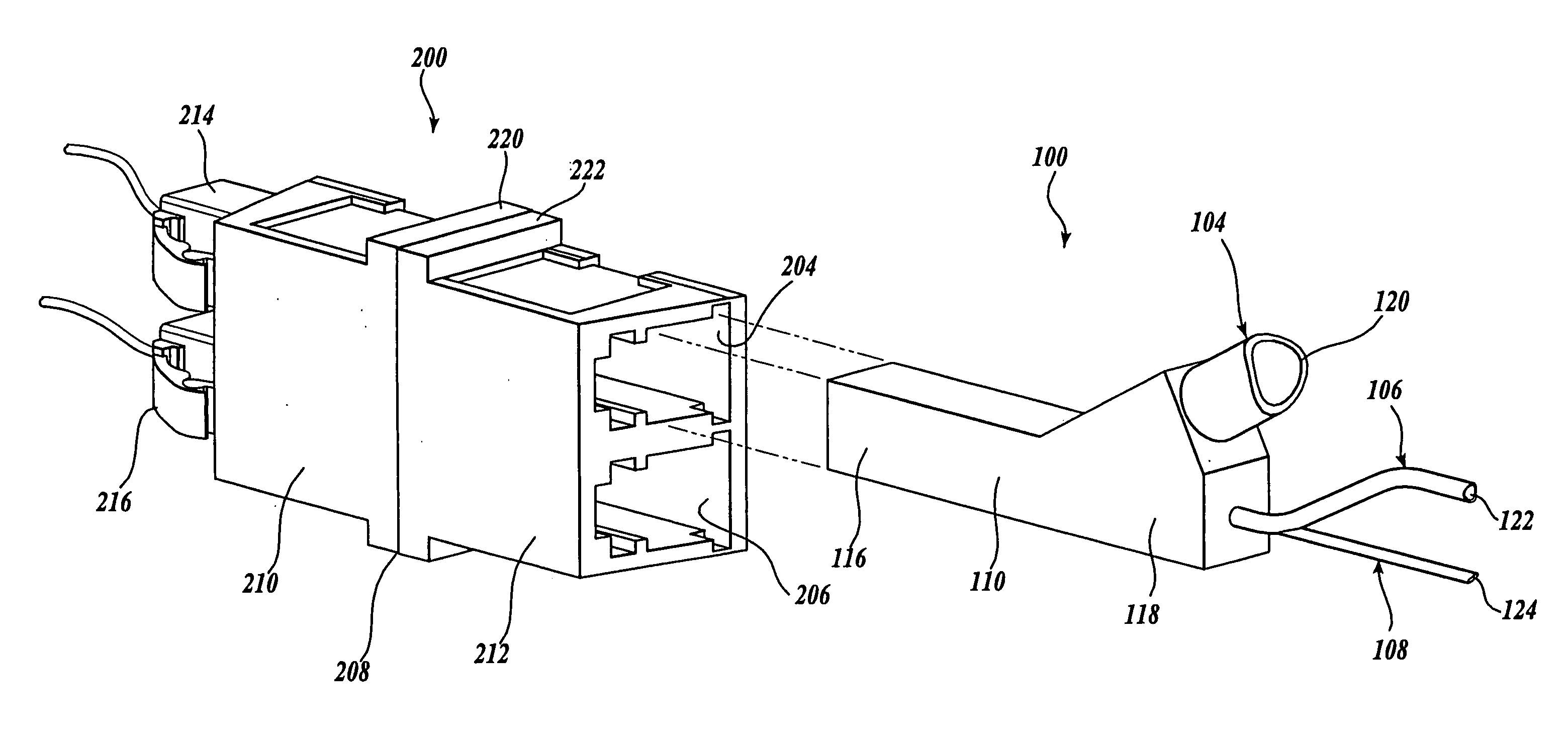
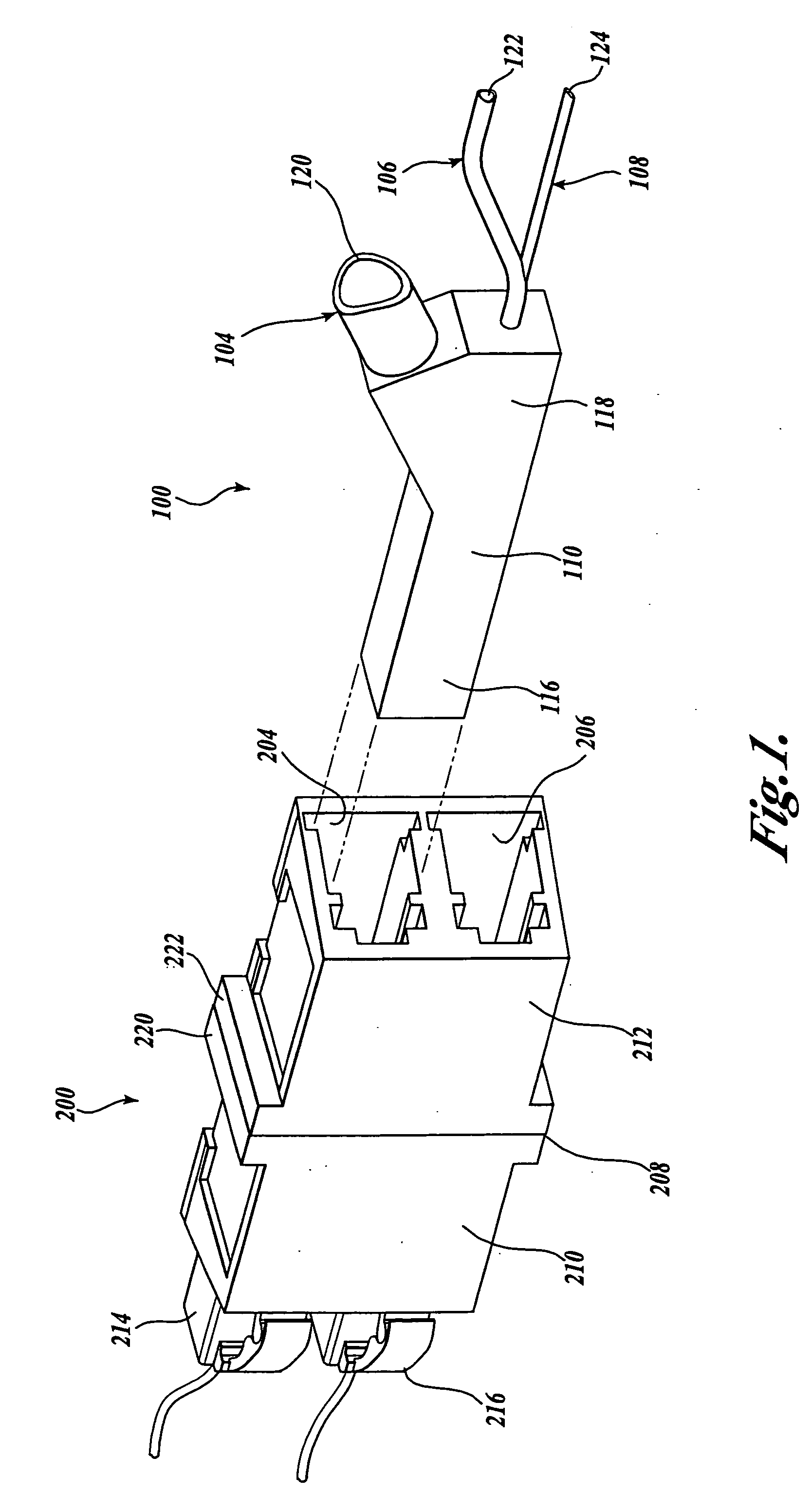
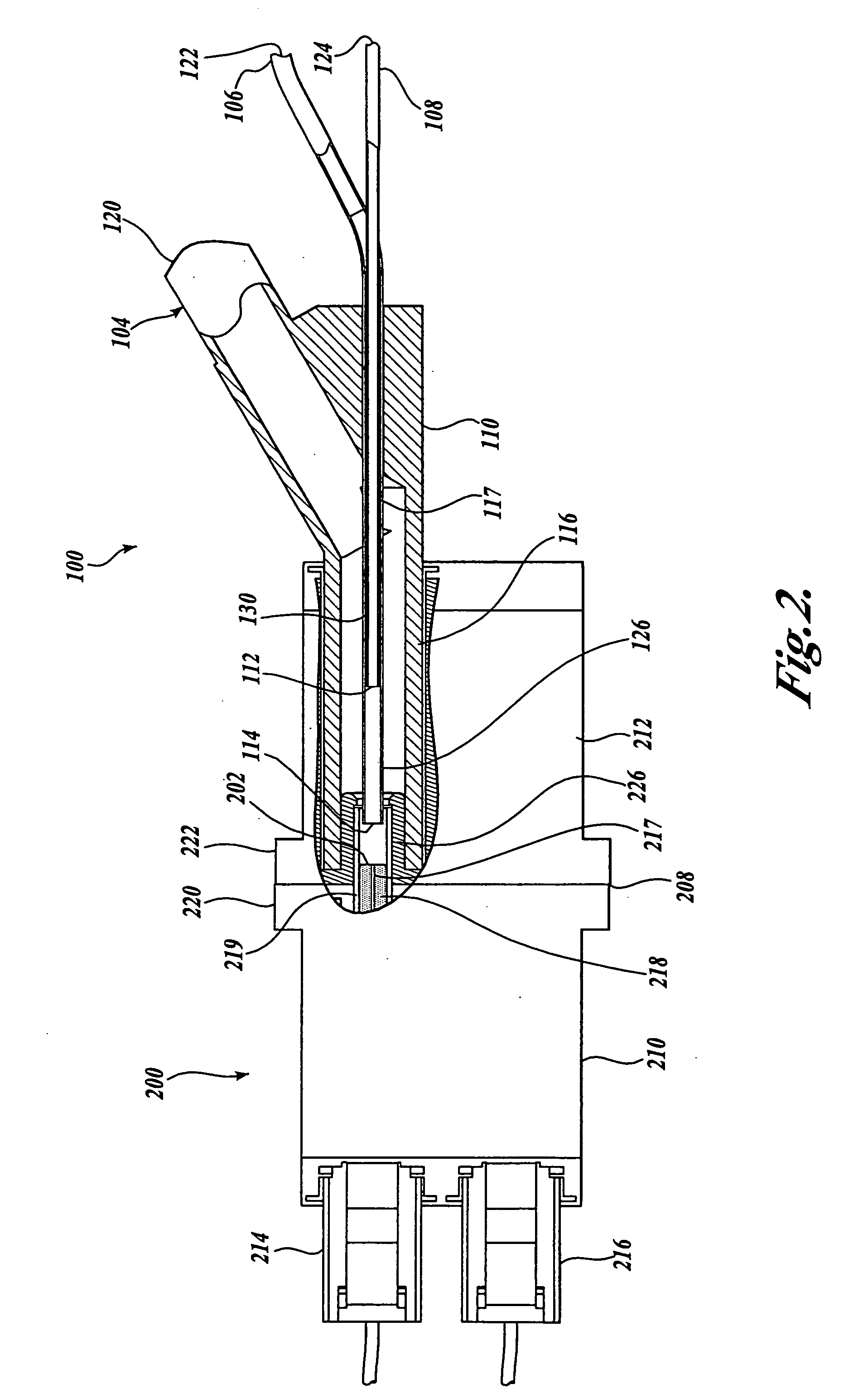
[0030] The present invention is a fiber-optic endface cleaning assembly for cleaning the endface of an optical fiber. While not limited to the following application, the cleaning assembly of the present invention is particularly suitable for cleaning an endface of an optical fiber contained in an interface device, which is defined as any assembly, device, or apparatus having an exposed fiber-optic endface therein or supported thereby. Examples of such an interface device include any one or more, or combination of, the following: an alignment sleeve, bulkhead adapter, transceiver, transmitter, detector, or connector. A bulkhead adapter is also sometimes referred to as a “mating adapter” or a “backplane adapter”, and their design and configurations vary greatly. For illustrative purposes only, the embodiments of the present invention will be described either in relation to a fiber-optic connector contained within a bulkhead adapter, or alternately, in relation to a fiber-optic connect...


PUM


Abstract

A cleaning apparatus (100) for cleaning an endface (202) of an optical fiber contained within an interface device (200) is provided. The cleaning apparatus includes a housing (110) having an interface portion (116) adapted to be received by the interface device. The cleaning apparatus also includes at least a first nozzle (126) operable to deliver a pressurized gas and a solvent upon the endface to aid in the removal of contaminants on the endface. A method for cleaning an endface of an optical fiber contained within an interface device is also provided. The method comprises the steps of inserting an interface portion within the interface device so as to position a nozzle in proximity to the endface of the interface device. The method further comprises the steps of directing a pressurized gas through the nozzle toward the endface and intermixing a solvent with the pressurized gas.

Description

CROSS-REFERENCE TO RELATED APPLICATION [0001] This application is a continuation of prior application Ser. No. 10 / 199,925 filed Jul. 18, 2002, priority from the filing date of which is hereby claimed under 35 U.S.C. § 120.FIELD OF THE INVENTION [0002] The present invention related generally to fiber-optic cleaning systems and, more specifically, to cleaning systems for cleaning fiber-optic endfaces. BACKGROUND OF THE INVENTION [0003] The proliferation of fiber-optic communications has led to its widespread implementation and use in industry, especially in the fields of telecommunications and data communications. It is well known in the industry that fiber-optic endfaces must be kept clean and undamaged within fiber-optic communication systems. A fiber-optic endface is the cross-sectional surface that is created when an optical fiber is cut for termination. The fiber-optic endfaces are typically supported by a connector that couples to a bulkhead adapter (also sometimes referred to a...

Claims


Application Information

Patent Timeline
IPC IPC(8): B08B3/02B08B5/02B08B11/02G02B6/38
CPCB08B3/02B08B5/02B08B11/02G02B6/3866G02B6/3807G02B6/381B08B2240/02
Inventor GERHARD, GREGORY J.
Owner VIAVI SOLUTIONS INC
Features
  • Generate Ideas
  • Intellectual Property
  • Life Sciences
  • Materials
  • Tech Scout
  • Unparalleled Data Quality
  • Higher Quality Content
  • 60% Fewer Hallucinations
Learn More