Variable flute helical-pitch rotary cutting tool

a rotary cutting tool and flute technology, applied in the field of rotary cutting tools, can solve the problems of poor finish on the machined part, poor finish associated with the traditional chatter-producing end mill, and limitation of thin-walled aluminum parts, so as to reduce chatter or resonance vibrations during use and improve the finish of milled parts

Inactive Publication Date: 2005-05-19
ROBBJACK CORP
View PDF28 Cites 39 Cited by
  • Summary
  • Abstract
  • Description
  • Claims
  • Application Information

AI Technical Summary

Benefits of technology

[0018] An object of the present invention is to provide a rotary cutting tool that reduces chatter or resonance vibrations during usage, thereby producing better finishes on milled parts.

Problems solved by technology

When a traditionally designed and sharpened end mill tool, frequently composed of carbide and carbide alloys, rotationally encounters a substance like aluminum or the like, the mill begins to “chatter,” whereby the rotating end mill's frequency of vibration (resonance frequency) self-excites and causes a poor finish on the machined part.
In addition to the poor finish associated with the traditional chatter-producing end mill is a limitation with thin-walled aluminum parts.
The end mill tool chatter may stress the thin-walled aluminum parts beyond structural limits and produce unacceptable parts.
Further, chattering can dull the cutting edge of an end mill and limit its useful life, thereby increasing costs for the milling operation and generating less precise machined parts than may be desired or required for a particular final function.

Method used


Image

  • Variable flute helical-pitch rotary cutting tool
  • Variable flute helical-pitch rotary cutting tool
  • Variable flute helical-pitch rotary cutting tool

Examples


Embodiment Construction

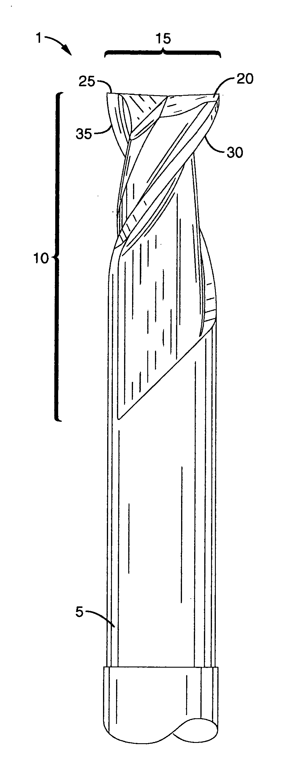
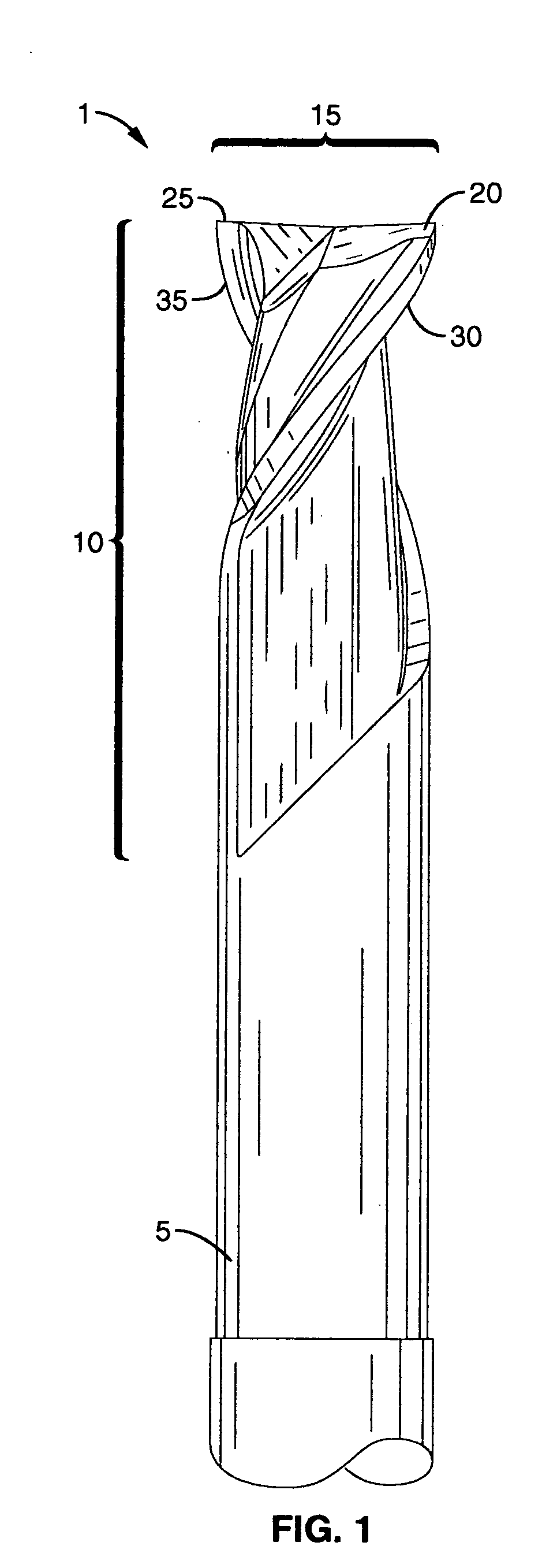
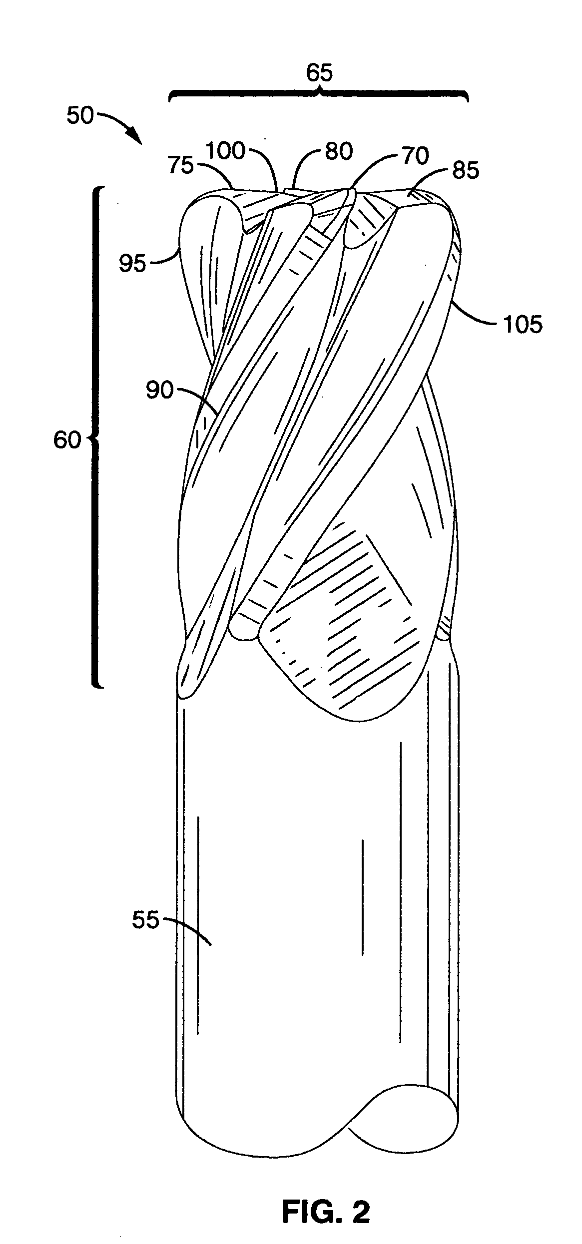
[0033] Referring more specifically to the drawings, for illustrative purposes the present invention is embodied in the apparatus generally shown in FIG. 1 through FIGS. 5A and 5B. It will be appreciated that the apparatus may vary as to configuration and as to details of the parts, and that the method may vary as to the specific steps and sequence, without departing from the basic concepts as disclosed herein.

[0034] Many rotary cutting tools are fabricated from various commercial grades of solid carbide and carbide alloy and are designed to machine parts formed from softer aluminum to harder stainless steels and related alloys. The subject invention is particularly useful in machining such parts where deep pockets and thin walls are encountered.

[0035] Generally, each rotary cutting tool comprises a shank, sometimes transitioning into a narrower neck (the machine utilizing the rotary cutting tool grips the tool by the shank). The shank extends to a cutting region with the cutting r...


PUM


Abstract

An rotary cutting tool is presented that has a shank region, a cutting region terminating in a cutting tip, at least one a flute formed within the cutting region beginning at the cutting tip and terminating at a distal location towards the shank region, and a cutting edge formed along an outer border of each flute. Each flute starts with a first helical-pitch proximate the cutting tip and changes to a second helical-pitch proximate the terminating distal location. When the rotary cutting tool has multiple paired flutes each set of paired flutes may be off-set from the next at other than a perpendicular alignment.

Description

CROSS-REFERENCE TO RELATED APPLICATIONS [0001] Not Applicable STATEMENT REGARDING FEDERALLY SPONSORED RESEARCH OR DEVELOPMENT [0002] Not Applicable INCORPORATION-BY-REFERENCE OF MATERIAL SUBMITTED ON A COMPACT DISC [0003] Not Applicable BACKGROUND OF THE INVENTION [0004] 1. Field of the Invention [0005] This invention pertains generally to a rotary cutting tool having at least one variable helical-pitch or helical-angle cutting flute. In particular, the subject invention discloses an rotary cutting tool having improved harmonic resonance stability characteristics produced by incorporating at least one cutting flute that begin at the end mill cutting tip with a first helical-pitch and gradually varies to a terminating second helical-pitch and when a plurality of paired flutes are present both variable helical-pitch and off-set spacing of the paired flutes minimizes vibrations. [0006] 2. Description of Related Art [0007] Rotary cutting tools or end mill tools have been utilized for va...

Claims


Application Information

Patent Timeline
Patent Type & Authority Applications(United States)
IPC IPC(8): B23C5/10
CPCB23C5/10B23C2210/0485Y10T407/1946B23C2250/16B23C2210/0492
Inventor MACARTHUR, MIKE
Owner ROBBJACK CORP
Why Eureka
Try Eureka