Torque transmission apparatus and case structure
- Summary
- Abstract
- Description
- Claims
- Application Information
AI Technical Summary
Benefits of technology
Problems solved by technology
Method used
Image

Examples
first embodiment
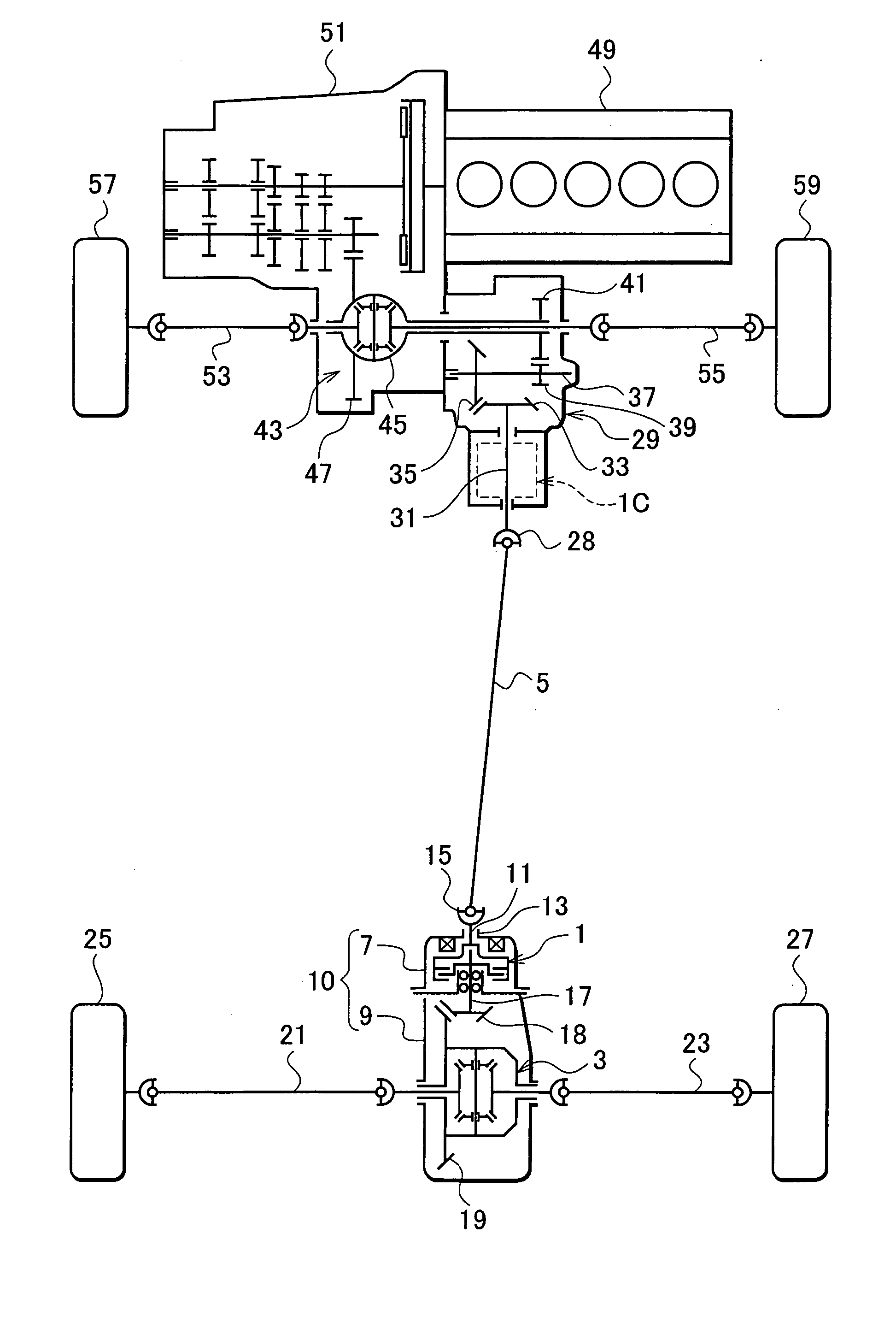
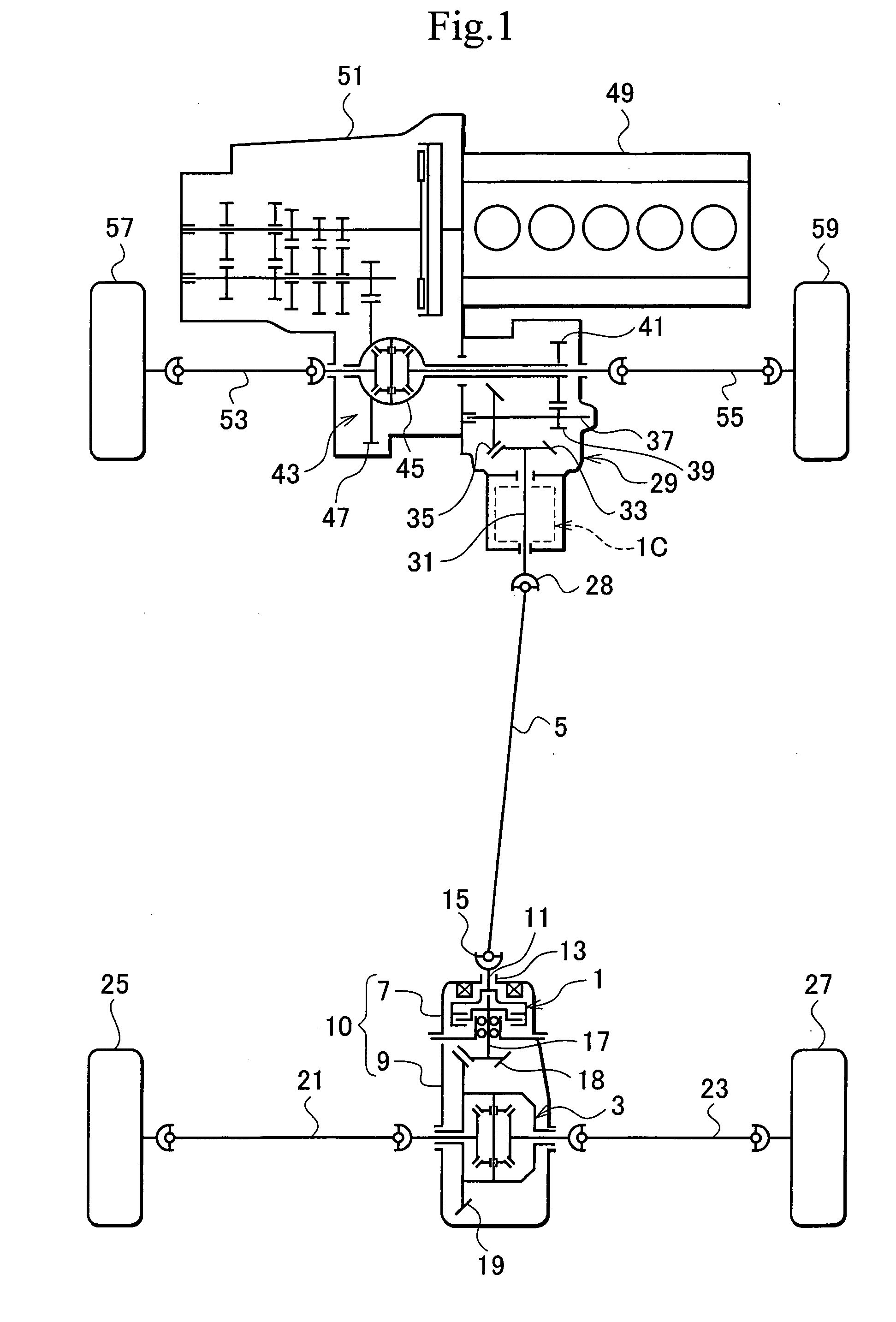
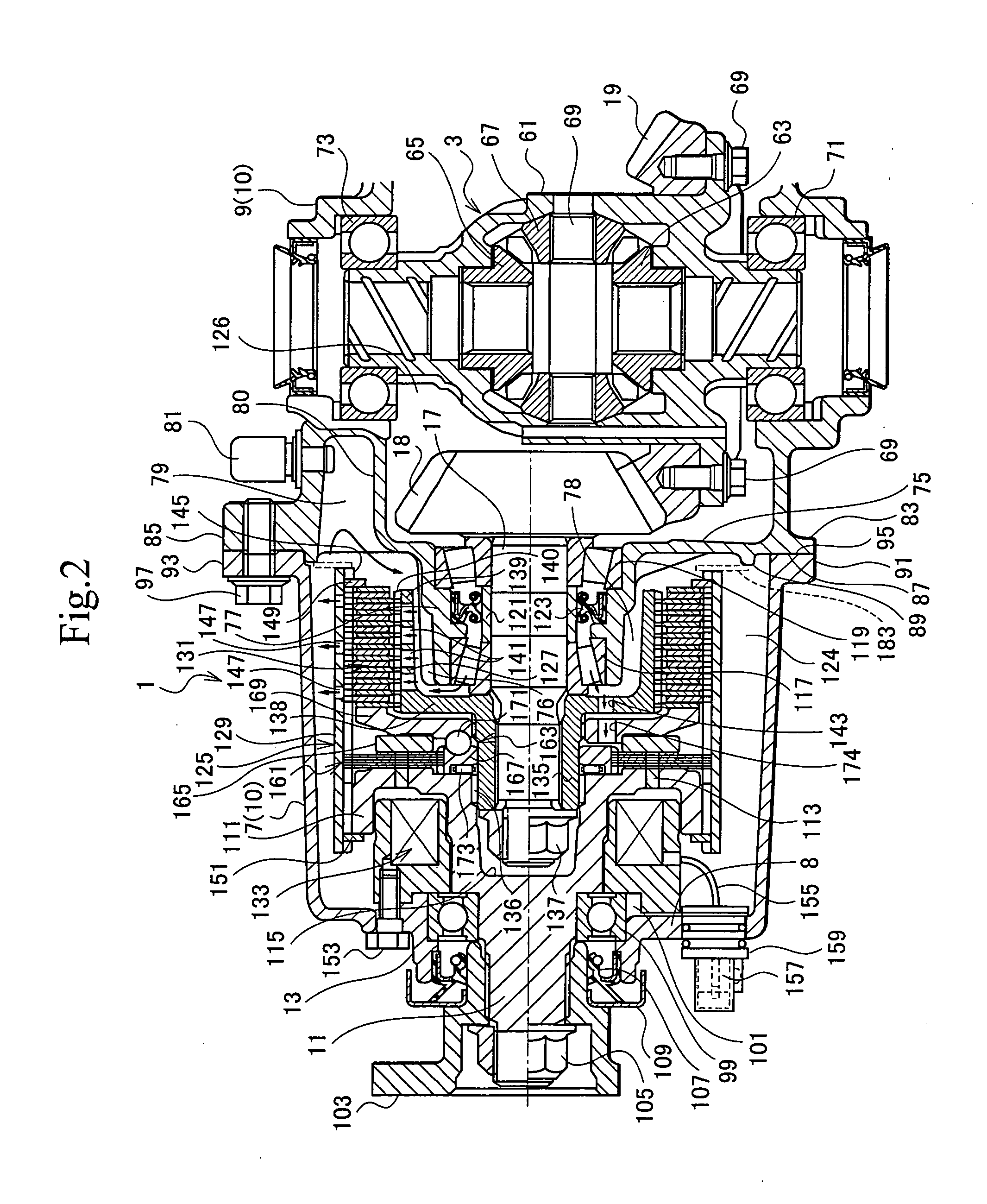
[0084] FIGS. 1 to 3 show the torque transmission apparatus according to the present invention, in which FIG. 1 is a skeleton plan view of a four wheel drive vehicle showing an arrangement of a torque transmission apparatus, FIG. 2 is an enlarged cross sectional view showing a mounting state of the torque transmission apparatus, in which an approximately upper left half shows an enlarged vertical cross sectional view, and the other shows an enlarged horizontal cross sectional view, and FIG. 3 is a side elevational view showing a part of the torque transmission apparatus by a cross section.
[0085] As shown in FIG. 1, a torque transmission coupling 1 serving as a torque control mechanism constitutes a second torque transmission mechanism is arranged between a rear differential 3 and a propeller shaft 5 in a four wheel drive vehicle of a transverse front engine and front wheel drive base (FF base).
[0086] The torque transmission coupling 1 is arranged within a carrier cover 7 serving as ...
embodiment 1
[0156] Accordingly, in the present embodiment, the main clutch 131 is positioned in the outer peripheries of the taper roller bearing 117 and the nut 137, whereby it is possible to make the length in the direction along the rotating axis entirely shorter, and it is possible to achieve approximately the same operations and effects as those of the
[0157] In addition, the nut 137 is tightened to the drive pinion shaft 17A in the penetrating state, and the clutch hub 127 is rotationally engaged with the end portion 185 of the drive pinion shaft 17 extending through the nut 137. It is possible to use the occupied volumetric capacity between the taper roller bearing 117, and the nut 137 and the main clutch 131 in common, and it is possible to securely make the entire length shorter while securing the sufficient oil space 187, 189 and 191.
[0158] Further, in the present embodiment, it is possible to securely lubricate the taper roller bearing 117, the main clutch 131, the cam mechanism 163,...
fourth embodiment
[0212] Accordingly, in the present embodiment, in addition to the operations and effects of the fourth embodiment, it is possible to sufficiently lubricate the taper roller bearing 117 by the gear oil even if the bearing housing portion 77E is made long and the bearing span is increased.
[0213]FIG. 9 shows a sixth embodiment according to the present invention and is a vertical cross sectional view of a torque transmission apparatus and a periphery thereof. A basic structure of the present embodiment is the same as the fifth embodiment in FIG. 8. Accordingly, a description will be given by attaching the same reference numerals or reference numerals obtained by attaching F to the same reference numerals to the structure portions or replacing E by F in correspondence to the fifth embodiment.
[0214] In the present embodiment, a bearing housing portion 77F serving as the first carrier portion and a building-up portion 2169F are slightly extended to protrude in a direction along the rotati...
PUM
 Abstract
Description
Claims
Application Information
 - Generate Ideas
- Intellectual Property
- Life Sciences
- Materials
- Tech Scout
- Unparalleled Data Quality
- Higher Quality Content
- 60% Fewer Hallucinations
Browse by: Latest US Patents, China's latest patents, Technical Efficacy Thesaurus, Application Domain, Technology Topic, Popular Technical Reports.
© 2025 PatSnap. All rights reserved.Legal|Privacy policy|Modern Slavery Act Transparency Statement|Sitemap|About US| Contact US: help@patsnap.com