
Signal processing device and signal processing method

a signal processing and signal processing technology, applied in the field of signal processing devices and signal processing methods, can solve the problems of not established a relationship, volume of computations, and inability to perform computations for an fft of the size of n/a

Inactive Publication Date: 2005-05-19
SONY CORP
View PDF12 Cites 7 Cited by
  • Summary
  • Abstract
  • Description
  • Claims
  • Application Information

AI Technical Summary

Benefits of technology

[0042] In view of the above described circumstances, it is therefore the object of the present invention to provides a signal processing device and a signal processing method for performing forward transform computations and inverse transform computations of MDCT at high speed for the purpose of realizing a linear transform of various digital signals such as audio signal and video signals and also performing a code string transform from a coding system into another, wherein the arithmetic operations of MDCT and those of IMDCT with a limited band are carried out at high speed by performing computations using an FFT with a short tap length as compared with a case where the band is not limited so as to reduce the work area and realize a higher speed for the arithmetic operations, whereas reducing the volume of computations such as multiplications or additions.
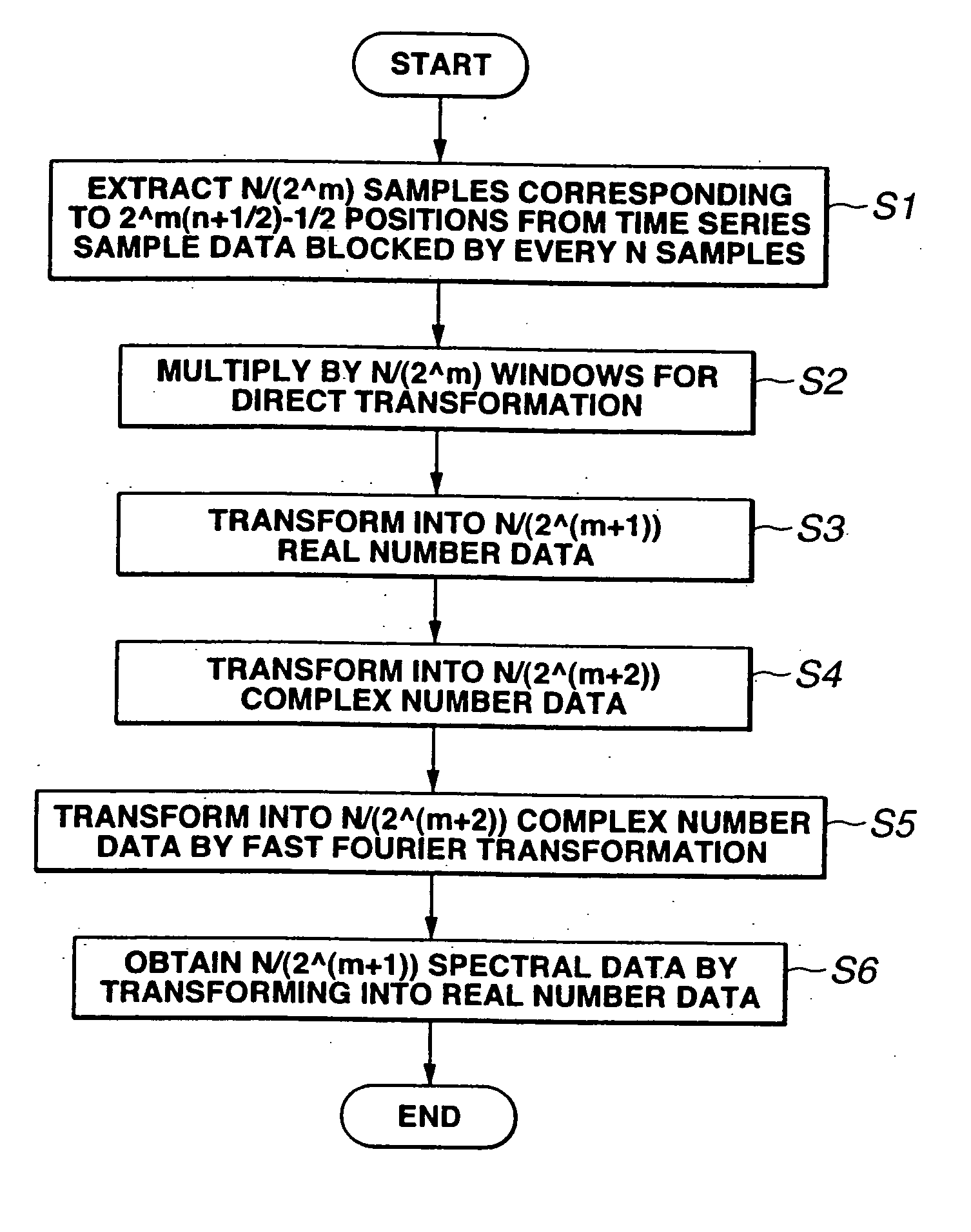
[0095] Thus, according to the invention, a linear forward transform can be realized for the purpose of a modified DCT to be carried out on N / 2{circumflex over ( )}(m) samples by way of computations for performing an FFT on a complex signal having a length of N / (2{circumflex over ( )}(m+2)) to consequently reduce the volume of computations and the work area required for the computations. Likewise, a linear inverse transform can be realized for the purpose of a modified DCT to be carried out on N / 2{circumflex over ( )}(m) independent spectrum input signals by way of computations for performing an FFT on a complex signal having a length of N / (2{circumflex over ( )}(m+2)) to consequently reduce the volume of computations and the work area required for the computations. Additionally, when converting a code encoded by a coding system into a code of the other system of two different coding systems using a modified DCT and the band of the original code may be narrowed, the size of the FFT for the inverse transform process of the modified DCT can be reduced from the ordinary size to realize a high speed transform operation. Likewise, when converting a code encoded by a coding system into a code of the other system of two different coding systems using a modified DCT and the band of the converted code maybe narrowed, the size of the FFT for the forward transform process of the modified DCT can be reduced from the ordinary size to realize a high speed transform operation.
[0096] Then, according to the invention, when using the modified discrete cosine transform for transforming a time series signal into a spectrum signal, the size of the fast Fourier transform is reduced from the normal size depending on the required band. Similarly, when converting a code encoded by a coding system into a code of the other system of two different coding systems using a modified discrete cosine transform, the volume of computations necessary for modified discrete cosine transform is reduced from the normal volume (required when the band is limited but the volume of computations of the MDCT and that of the IMDCT are not limited) depending on the required band. As a result, the volume of arithmetic operations including the number of multiplications and that of additions can be reduced to by turn reduce the work area required for the computations and realize a high speed transform operation.
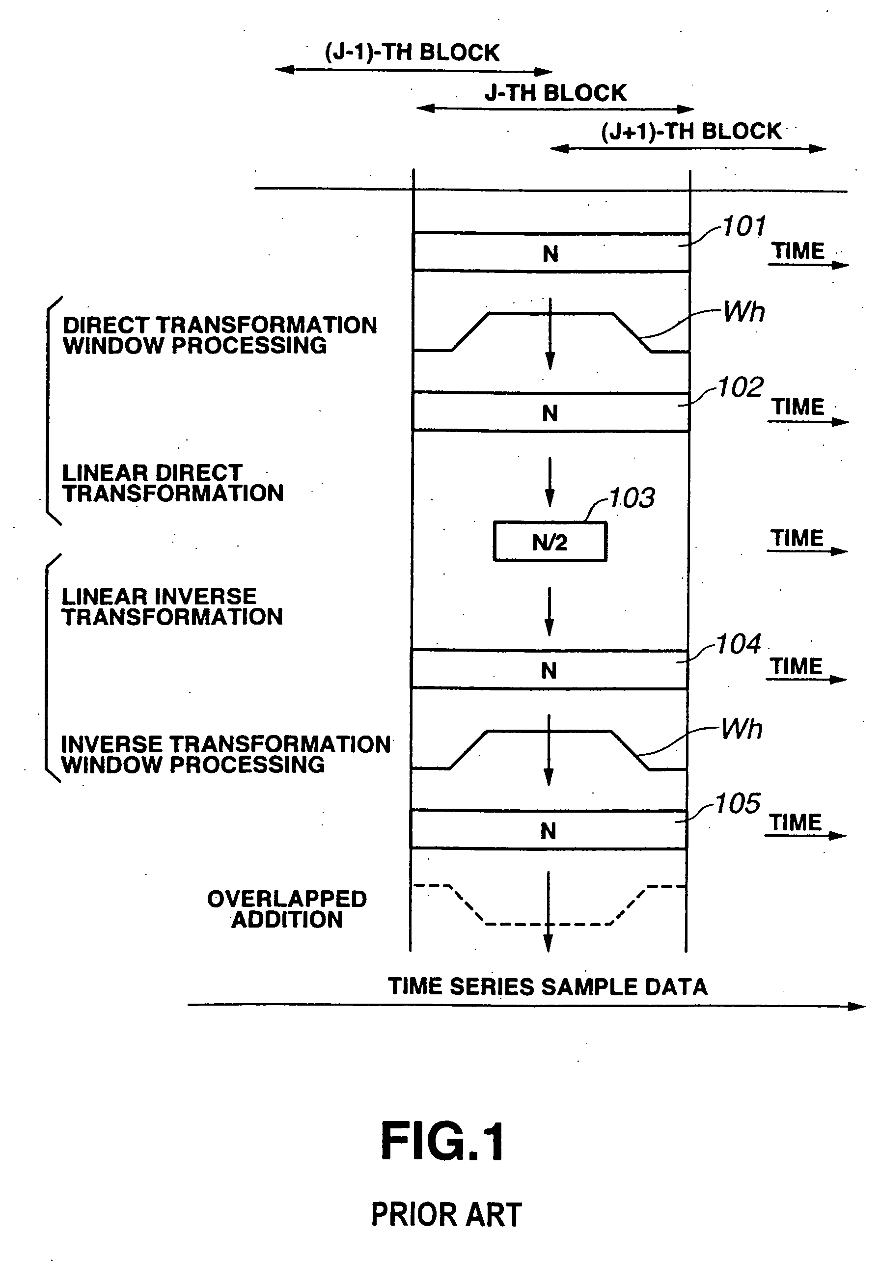
[0097] More specifically, according to the invention, for producing. N / 2 spectrum data obtained by directly performing a modified DCT (MDCT) on N time series sample data cut out so as to make each of the blocks overlap the rear half (50%) of the preceding block and the front half (50%) of the succeeding block, the computations of direct MDCT can be performed efficiently by using an FFT with a length of N / (2{circumflex over ( )}(m+2)) if the required number of spectrums is N / (2{circumflex over ( )}(m+1)) after the transform so that the volume of computations can be reduced depending on the capacity of the coding device being used and the quality of the codes involved. Then, as a result, it is possible to provide an encoder and a code string transform device having a simple configuration and operating efficiently for audio signals.
[0098] Additionally, according to the invention, for producing N time series sample data by inversely performing a modified DCT (MDCT) on N / 2 independent spectrums, the computations of inverse MDCT can be performed efficiently by using an FFT with a length of N / (2{circumflex over ( )}(m+2)) if the required number of spectrums is N / (2{circumflex over ( )}(m+1)) before the transform so that the volume of computations can be reduced depending on the capacity of the coding device being used and the quality of the codes involved. Then, as a result, it is possible to provide a decoder and a code string transform device having a simple configuration and operating efficiently for audio signals.

Problems solved by technology

However, this transform technique is accompanied by the problem of block distortion that the discontinued boundary of adjacent blocks is perceived as noise.
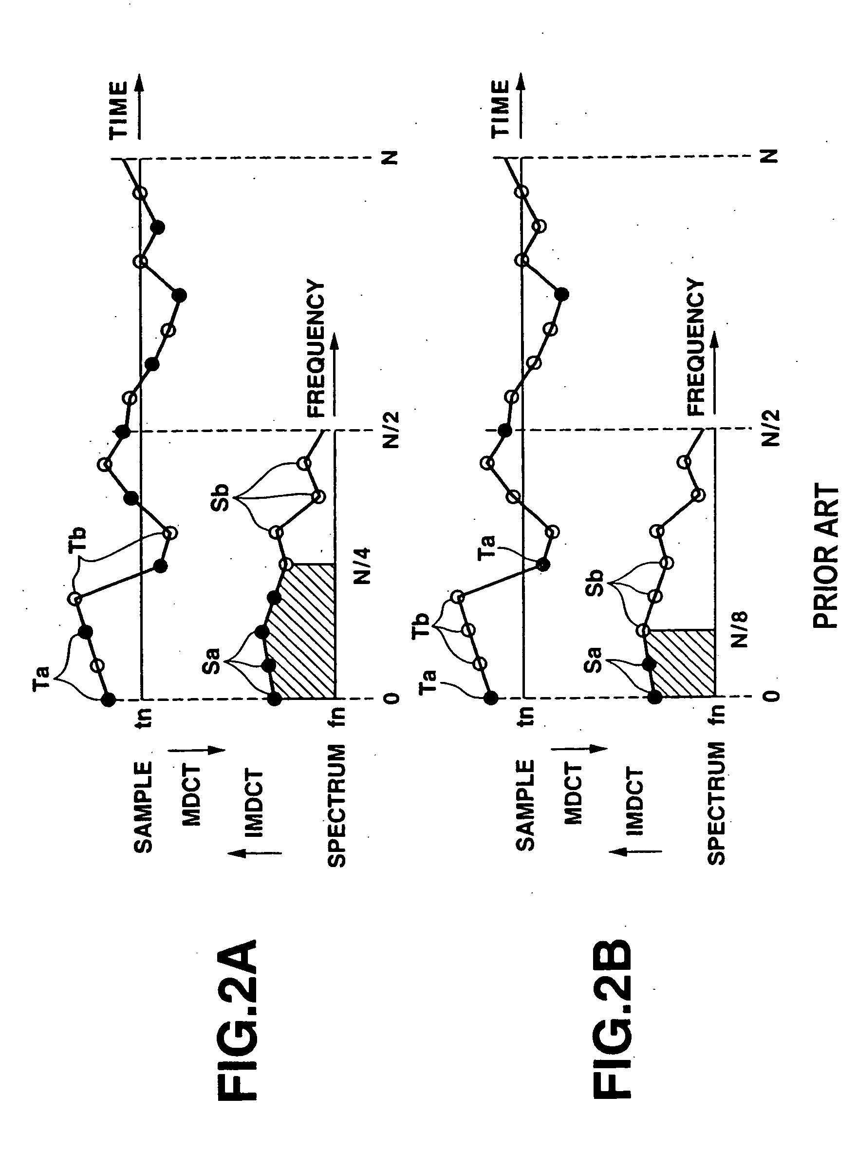
However, in a device for high efficiency coding / decoding using MDCT and IMDCT, there may be cases where it is desirable to reduce the volume of computations by limiting the frequency band required for decoding particularly when the processing capacity of the device is small.
However, since Z01 of the above instance is a complex number unlike the case of Japanese Patent Application Laid-Open No. 5-183442, there is not established a relationship where the sum and the difference of an even number and an odd number for n become complex conjugates.
Then, as a result, it is not possible to perform computations for an FFT of the size of N / (2{circumflex over ( )}(m+2)).

Method used


Image

  • Signal processing device and signal processing method
  • Signal processing device and signal processing method
  • Signal processing device and signal processing method

Examples


Embodiment Construction

[0123] Now, the present invention will be described in greater detail by referring to the accompanying drawing that illustrate preferred embodiments of the invention.

[0124] Firstly, the principle of computations that is adopted to the present invention will be discussed before describing specific embodiments of signal processing device and signal processing method according to the invention.

[0125] When performing computations of MDCT (modified DCT) with a signal processing device and a signal processing method according to the invention, formula (28) below is used to extract N / (2{circumflex over ( )}m) samples corresponding to 2{circumflex over ( )}m(n+{fraction (1 / 2)})−{fraction (1 / 2)} positions out of the time series sample data that are divided into blocks, each comprising N samples. Y21⁡(k)=⁢∑n=0N / 2m-1⁢X21⁡(2m⁢(n+12)-12)⁢cos⁢(π⁡(2⁢k+1)⁢(2m+1⁢n+N / 2+2m)2⁢N),⁢⁢for⁢ ⁢0≤k≤N2m+1-1(28)

[0126] Then, the input signals X21 are multiplied by window H21 to produce X22, using formula (29) ...


PUM


Abstract

A signal processing device and method for performing a code string transform by transforming a time series signal with a frequency band from 0 to 20 kHz from a coding system into another, wherein the arithmetic operations of MDCT and IMDCT with a limited frequency band from 0 to 15 kHz are carried out at high speed by performing computations using an FFT operation with a short tap length in the IMDCT processing operation. This allows a reduced work area and a higher speed for arithmetic operations by reducing the number of multiplications and additions when performing MDCT operations, IMDCT operation and / or transforming code strings between different coding system.

Description

RELATED APPLICATION DATA [0001] The present application claims priority to Japanese Application No. P2000-095310 filed Mar. 29, 2000, which application is incorporated herein by reference to the extent permitted by law. BACKGROUND OF THE INVENTION [0002] This invention relates to a signal processing device and a signal processing method for performing forward transform computations and inverse transform computations of so-called improved discrete cosine transform (or modified DCT) at high speed for the purpose of realizing a linear transform of various digital signals such as audio signals and video signals and also for performing a code string transform from a coding system into another at high speed. [0003] The orthogonal transform coding is known as a high efficiency coding technique adapted to high efficiency bit compression of a signal comprising time series sample data such as audio signal. With this transform coding technique, the input signal is subjected to an orthogonal tr...

Claims


Application Information

Patent Timeline
Patent Type & Authority Applications(United States)
IPC IPC(8): G10L19/02G06F17/14G10L19/00G10L19/032H03M7/30H04N19/40H04N19/426H04N19/60H04N19/625H04N19/80H04N19/86
CPCG06F17/147
Inventor KIKUCHI, ATSUSHIHONMA, HIROYUKITSUTSUI, KYOYA
Owner SONY CORP
Learn More