Composite tape laying apparatus and method

a technology of composite tape and laying equipment, which is applied in the direction of paper hanging, mechanical control devices, instruments, etc., can solve the problems of excessive downtime, complex and expensive apparatus and methods used to automate the lamination of various structural shapes with multiple layers of continuous fibers preimpregnated with resin binder, and increase the cost of manufacture. , to achieve the effect of maximizing material throughput, high speed deposition and simple procedur

Active Publication Date: 2005-05-26
TRELLEBORG SEALING SOLUTIONS GERMANY
View PDF3 Cites 179 Cited by
  • Summary
  • Abstract
  • Description
  • Claims
  • Application Information

AI Technical Summary

Benefits of technology

[0009] It has now been discovered by the present applicants that a significantly simpler procedure enables satisfactory laydown of a fiber prepreg in a continuous automated manner. More particularly, the present apparatus employs a novel laterally moving head member for relatively high speed deposition of the fiber prepreg in order to laminate assorted aircraft, aerospace and industrial structures. In so doing, the present apparatus includes a novel cut and restart mechanism enabling the tape to be cut while still being fed after removal of the customary backing layer. Such manner of relatively continuous tape transport in the present apparatus maximizes material throughput during the reinforcement procedure for higher operating efficiency. The presently modified head member applies the unbacked reinforcement tape to the surface of the structural shape being laminated with conventional type ...

Problems solved by technology

The apparatus and methods now in use to automatedly laminate various structural shapes with multiple layers of continuous fibers preimpregnated with a resin binder are both complex and expensive.
The prior art techniques for laydown of such tape to reinforce the underlying structural shap...

Method used


Image

  • Composite tape laying apparatus and method
  • Composite tape laying apparatus and method
  • Composite tape laying apparatus and method

Examples


Embodiment Construction

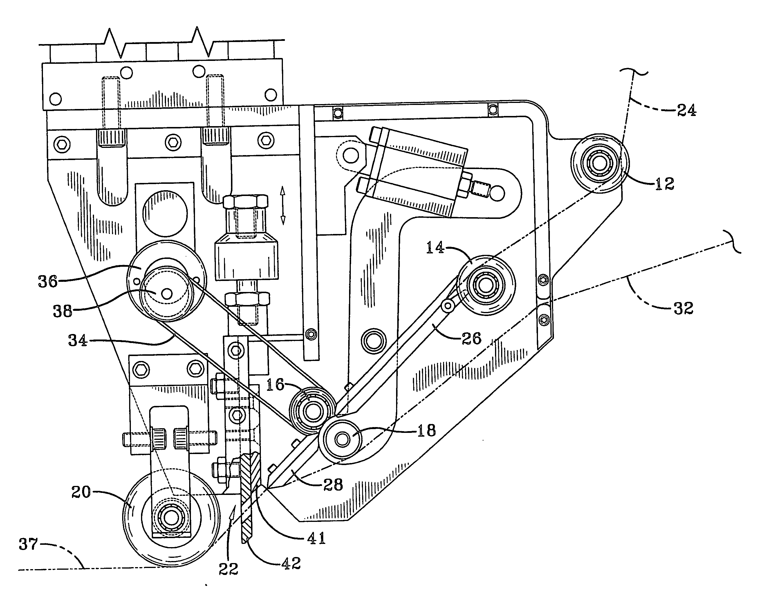
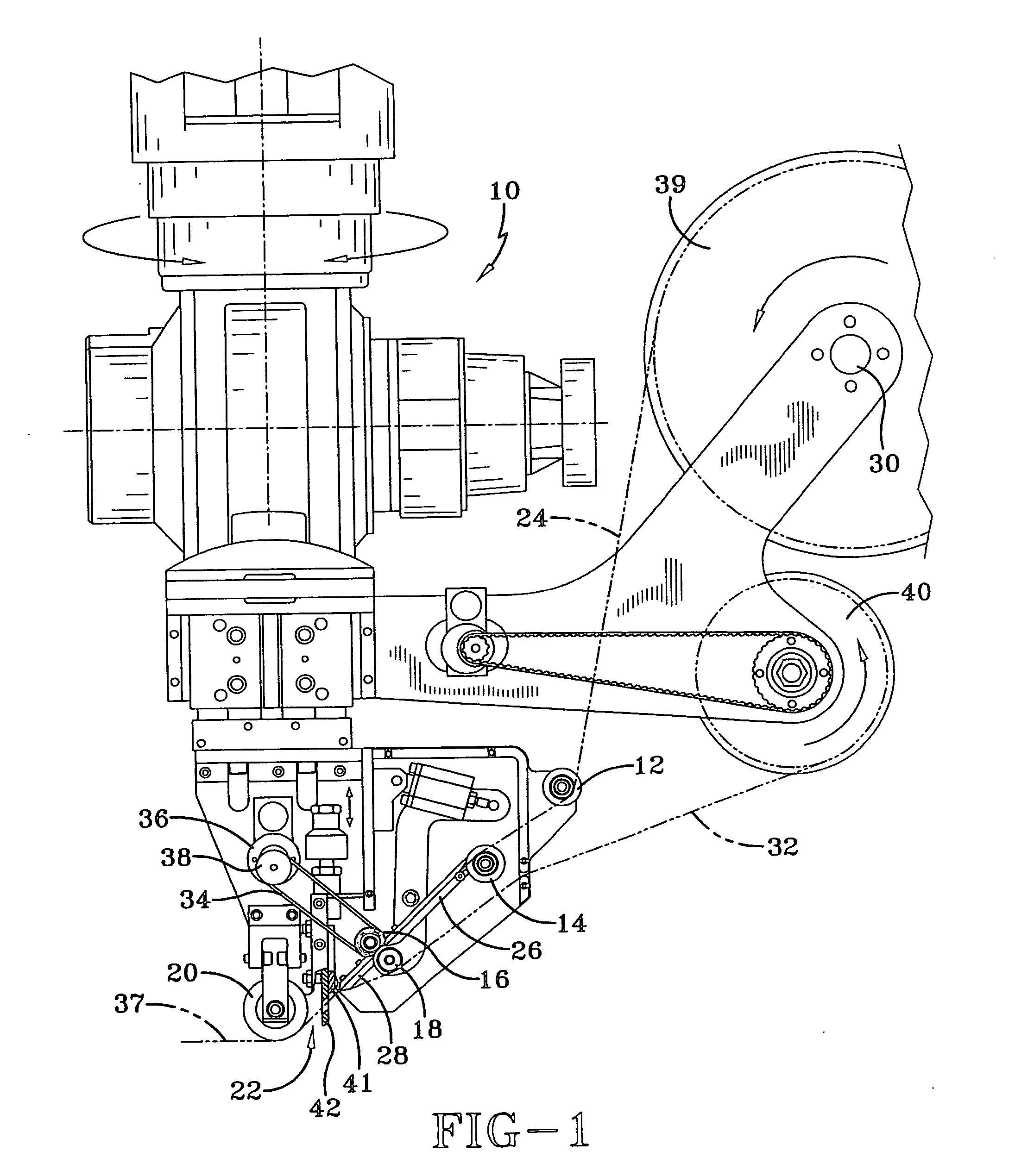
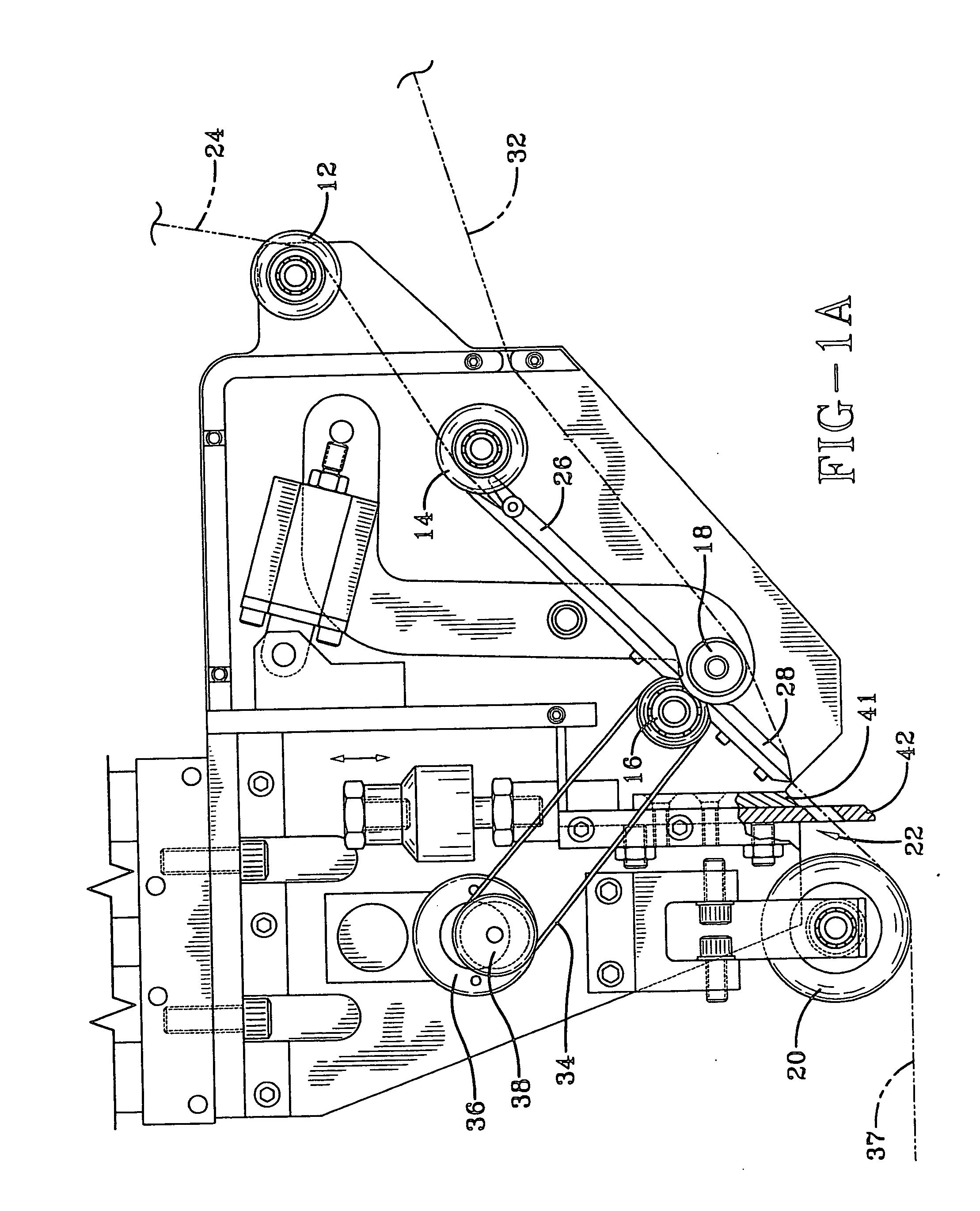
[0015] Referring to the drawings, there in shown in FIG. 1 a schematic side view of a typical tape laying apparatus according to the present invention. Basically, said movable tape laying member 10 houses a first pair of operationally cooperating guide or idler rollers 12 and 14, a second pair of operationally cooperating pinch rollers 16 and 18, a compaction roller 20 and a further included motorized guillotine cutter mechanism 22. As can be observed, the resin impregnated tape 24 being continuously transported in said tape laying member is guided during passage with suitably disposed chute guides 26 and 28. Rotating spool 39 supplies the tape being processed in said tape laying member and includes a conventional friction braking device 30 to avert tape unwinding when not being pulled forward by cooperating motor driven spool 40. Motor driven spool 40 continuously removes the backing layer 32 from the supplied tape by simply rewinding the separated backing layer about the spool cir...


PUM

PropertyMeasurementUnit
Lengthaaaaaaaaaa
Speedaaaaaaaaaa
Transport propertiesaaaaaaaaaa

Abstract

A fully automated method and apparatus is disclosed to laminate various structural articles with a layer of resin impregnated fiber tape. The tape laying member removes a releasable backing layer from the tape being employed, then deposits the unbacked tape on the surface of the structural article, and finally severs the end of the tape being deposited. An automated cut and restart procedure is employed in the present tape laying member to increase tape throughput.

Description

BACKGROUND OF THE INVENTION [0001] This invention relates generally to an improved method and apparatus for continuously applying a composite fiber tape to form various laminated articles and, more particularly, to doing so with a resin prepreg tape in a more simple and effective manner. [0002] Various apparatus and methods to apply or lay composite fiber tapes formed with continuous fibers preimpregnated with a resin binder are already well known. For example, there is described in U.S. Pat. No. 3,574,040 an apparatus for this purpose which automatedly peels the backing layer off this type composite tape before applying the unbacked tape to reinforce various aircraft and aerospace structural parts. There is also described in U.S. Pat. No. 4,557,783 a different automated apparatus for separating the backing layer from a thermoset resin prepreg tape and applying the unbacked tape with compaction while further storing said backing layer. In U.S. Pat. No. 4,591,402 there is further des...

Claims


Application Information

Patent Timeline
IPC IPC(8): B29C70/38
CPCB29C70/388B29C70/545Y10T156/1077Y10T156/1778Y10T156/1348Y10T156/1085Y10T156/1795Y10T156/1343Y10T156/1052Y10T156/1788B29C2793/0027
Inventor HAUBER, DAVID E.LANGONE, ROB J.MARTIN, JAMES P.MILLER, SCOTT F.PASANEN, MICHAEL J.
Owner TRELLEBORG SEALING SOLUTIONS GERMANY
Why Eureka
Try Eureka