

Binder resin and sliding resistor
a technology of sliding resistor and binding resin, which is applied in the direction of resistor details, non-metal conductors, conductors, etc., can solve the problems of increasing contact resistance, and achieve excellent sliding durability and excellent sliding durability
- Summary
- Abstract
- Description
- Claims
- Application Information
AI Technical Summary
Benefits of technology
Problems solved by technology
Method used
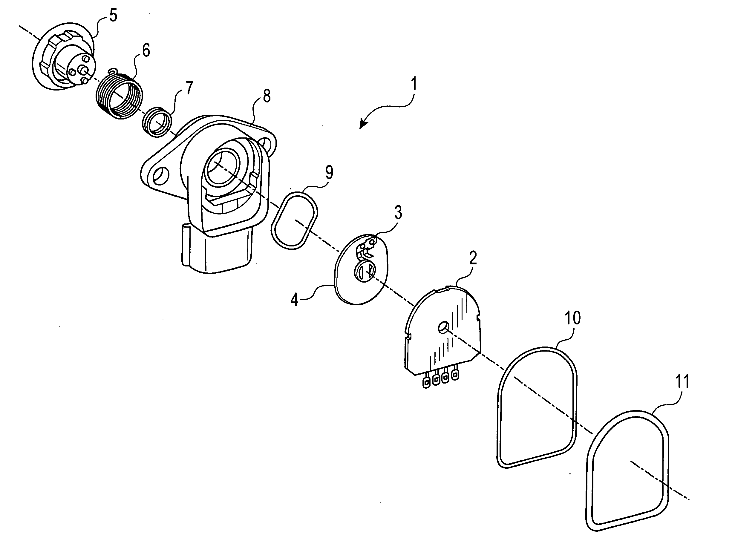
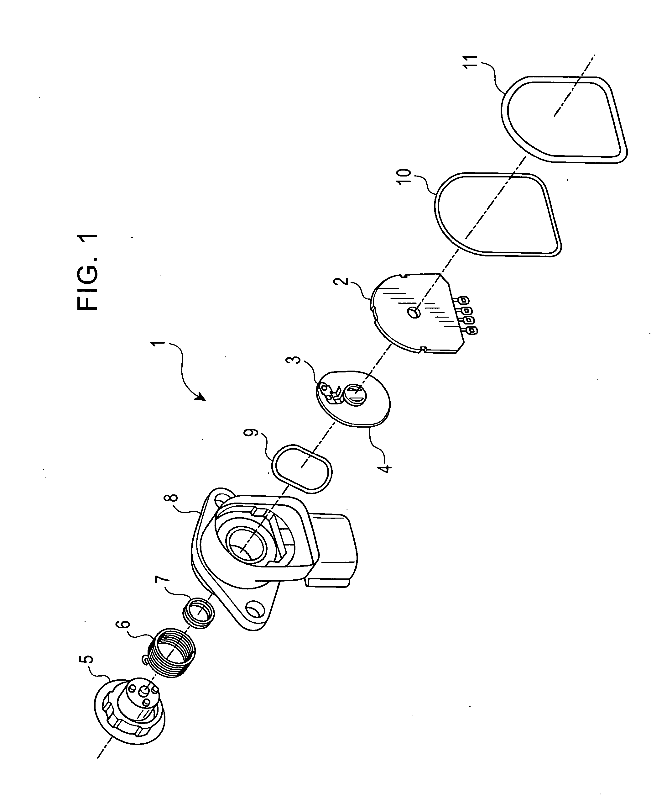
Image

Examples
example 1
[0053] Binder resins were synthesized in the following procedure. First, 29.2 g of aminophenoxybenzene (APB) and 64.4 g of benzophenonetetracarboxylic dianhydride (BTDA) were dissolved into about 300 g of tetrahydrofuran (THF) and were reacted in the presence of an antioxidant. Then, 23.4 g of aminophenylacetylene was added to prepare a solution containing the oligomer (I). Subsequently, a dehydrogenating agent was added to the solution to prepare a mixed solution of the oligomer (I) and the oligomer (II).
[0054] Half of the mixed solution was taken, and THF was removed to obtain about 44 g of binder resin A (a mixture of the oligomer (I) and the oligomer (II)). A sample was prepared by the KBr method and was analyzed with an infrared spectrometer. The analysis showed that the ratio of the oligomer (I) to the oligomer (II) in the binder resin A was 0.2, which was the ratio of the peak at 1,550 cm−1, namely the absorption wavelength of the amic acid, to the peak at 940 cm−1, namely t...
PUM
| Property | Measurement | Unit |
|---|---|---|
| Electrical conductor | aaaaa | aaaaa |
Abstract
Description
Claims
Application Information