System and method for managing projector bulb life

Active Publication Date: 2005-05-26
DELL PROD LP
7 Cites 39 Cited by

AI-Extracted Technical Summary

Problems solved by technology

However, obtaining high resolution images from CRT displays is difficult and often involves the use of bulky devices with relatively high power consumption.
One difficulty that remains with consumer acceptance of projector display devices is that the projector bulbs typically used in projector devices are expensive ultra high pressure mercury vapor or xenon halogen lamps that have a generally s...

Benefits of technology

[0008] In accordance with the present invention, a method and system are provided which substantially reduce the disadvantages and problems associated with previous methods and systems for managing a projector bulb life. A luminance feed back control loop senses luminance output by a projector bulb and provides a control signal to the projector bulb's power driver to maintain brightness output from the bulb so that the bulb has a desired performance, such as maximum life or maximum brightness over the bulb's life.
[0009] More specifically, a bulb is illuminated by a power driver that provides variable power to the bulb to generate variable brightness to illuminate information formed as an image, such as with a DMD or LCD display device. Bulb brightness is sensed by a luminance sensor and provided to a luminance feedback controller as a sense signal, such as a voltage. The luminance controller generates an error control signal that is fed back to the power driver to compensate for changes in bulb performance over time, such as arc length induced bulb brightness changes related to bulb aging. The luminance controller manages bulb luminance to obtain desired bulb performance parameters. In a maximum life mode, the luminance controller restricts bulb brightness to a threshold value by reducing the pow...

Abstract

Projector bulb life is managed to achieve desired performance parameters, such as a maximum life mode or maximum brightness mode, by sensing bulb luminance and applied the sensed luminance with a luminance feedback controller to drive the bulb to achieve the desired performance parameter. For instance, in maximum life mode the luminance feedback controller reduces power applied to the bulb to restrict bulb luminance to a maximum luminance setpoint when greater luminance is available with a newer bulb. In maximum brightness mode, the luminance feedback controller increases power applied to the bulb to increase bulb luminance if the sensor senses luminance below a threshold due bulb wear. Bulb life management improves project image illumination to display information in a variety of projector types, including digital mirror devices and liquid crystal displays.

Application Domain

Technology Topic

Image

  • System and method for managing projector bulb life
  • System and method for managing projector bulb life
  • System and method for managing projector bulb life

Examples

  • Experimental program(1)

Example

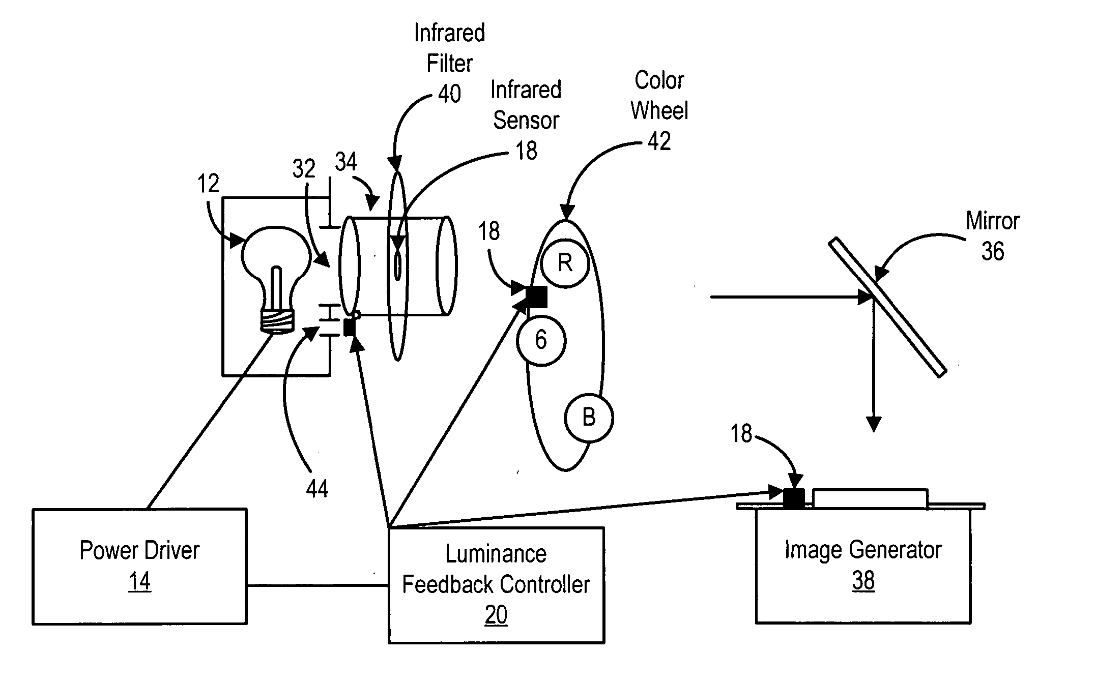
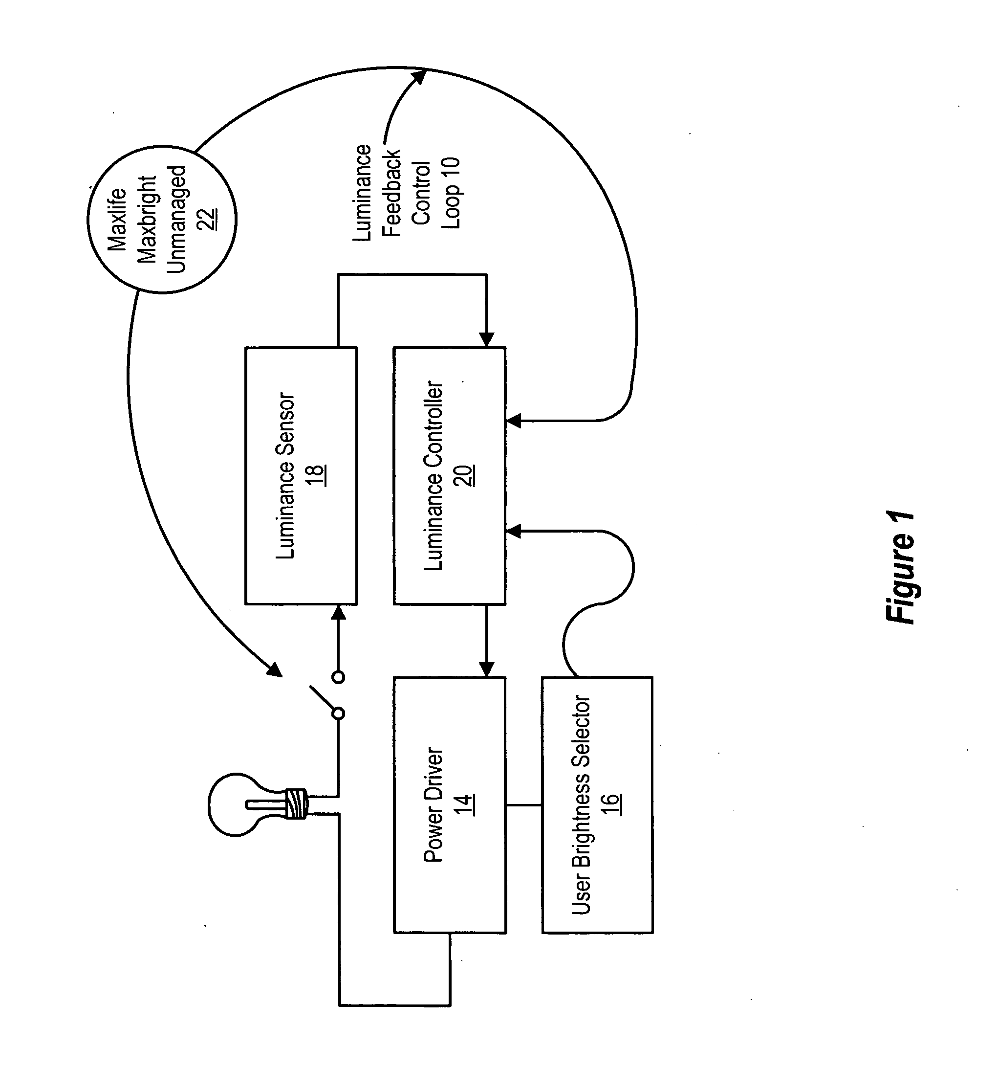
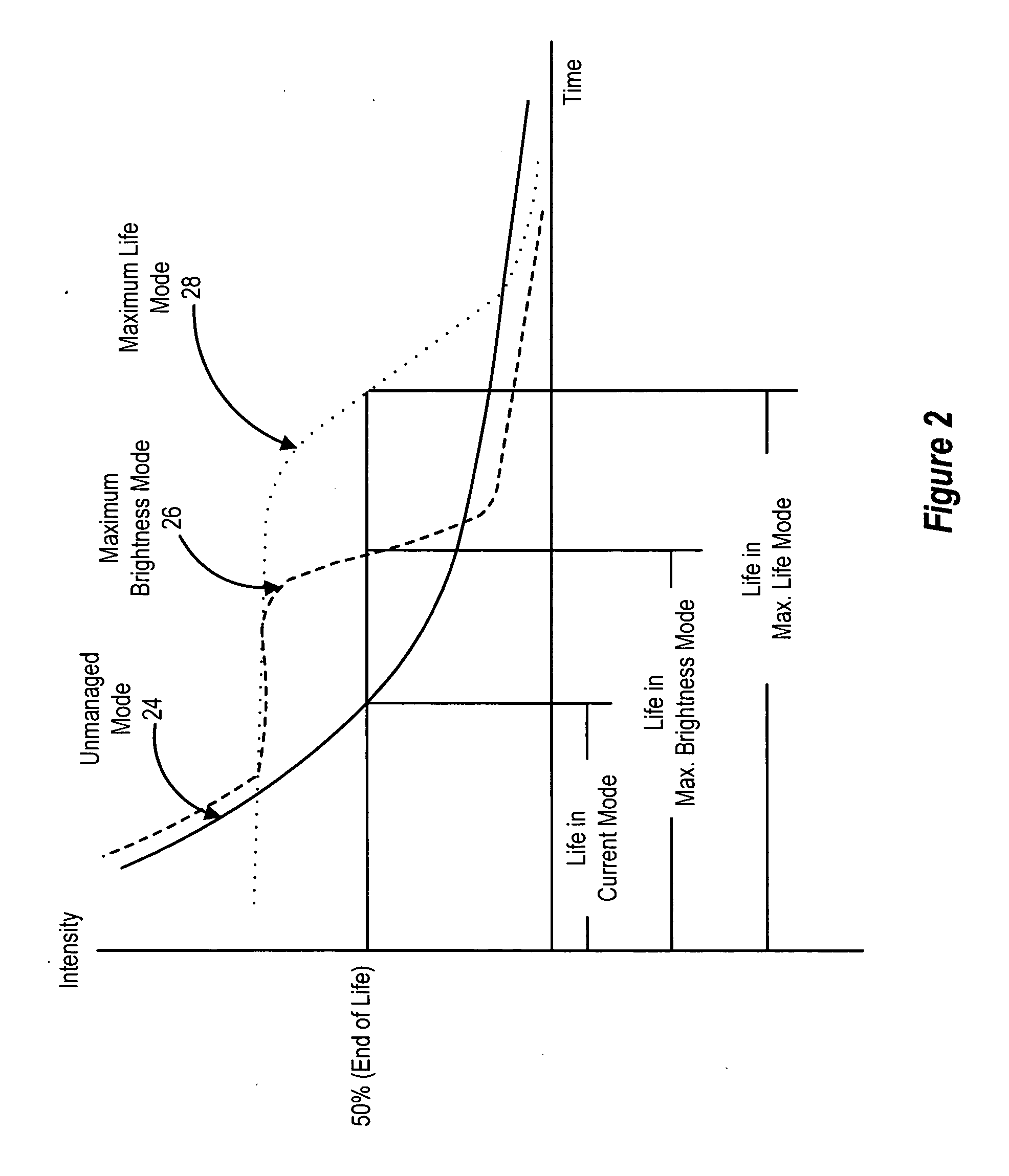
[0016] Projector bulb life management enhances the display of information, such as that generated by an information handling system, by illuminating an image having the information with a luminance designed to achieve desired bulb performance parameters, such as maximized life or maximized brightness over the life of a bulb. For purposes of this disclosure, an information handling system may include any instrumentality or aggregate of instrumentalities operable to compute, classify, process, transmit, receive, retrieve, originate, switch, store, display, manifest, detect, record, reproduce, handle, or utilize any form of information, intelligence, or data for business, scientific, control, or other purposes. For example, an information handling system may be a personal computer, a network storage device, or any other suitable device and may vary in size, shape, performance, functionality, and price. The information handling system may include random access memory (RAM), one or more processing resources such as a central processing unit (CPU) or hardware or software control logic, ROM, and/or other types of nonvolatile memory. Additional components of the information handling system may include one or more disk drives, one or more network ports for communicating with external devices as well as various input and output (I/O) devices, such as a keyboard, a mouse, and a video display. The information handling system may also include one or more buses operable to transmit communications between the various hardware components.
[0017] Referring now to FIG. 1, a block diagram depicts a luminance feedback control loop 10 operable to achieve desired projector bulb performance parameters, such as maximized bulb life or maximized bulb brightness. A projector bulb 12 provides illumination for display of information based on the level of power provided by a power driver 14. Brightness for bulb 12 is selectable by a user through a user brightness selector 16, which manually controls the power applied to bulb 12 by power driver 14. A luminance sensor 18 is disposed proximate to bulb 12 to sense the luminance provided by bulb 12 and output a sense signal proportional to the sensed luminance, such as a voltage provided by a voltage converter circuit. The voltage output by luminance sensor 18 is compared with a setpoint voltage by luminance controller 20 to generate a difference signal amplified as an error signal and fed back to power driver 14 in a closed-loop feedback form. The voltage output to bulb 12 by power driver 14 is thus increased or decreased depending on the sign and magnitude of the error signal from luminance controller 20. Luminance controller 20 applies a control algorithm to provide a desired projection bulb luminance that achieves a desired projection bulb performance parameter, such as maximum life or maximum brightness over the life of bulb 12. In alternative embodiments, other feedback signals may be used, such as current, duty cycle or other lamp-input parameters that define a control error correction signal.
[0018] Luminance controller 20 alters the power applied to bulb 12 by power driver 14 to compensate for changes in bulb luminance over a bulb's life. Generally, error correction signals impact bulb luminance output when user brightness selector 16 calls for a high brightness that is close to or at the maximum brightness of bulb 12. With newer bulbs, luminance controller 20 tends to decrease the output of power driver 14 so that luminance output by bulb 12 decreases in a tradeoff that increases the overall life of bulb 12. With older bulbs, luminance controller 20 tends to increase the output of power driver 14 so that luminance output by bulb 12 increases in a tradeoff that decreases the remaining life of bulb 12. The error signal correction provided by luminance controller 20 depends in part on the type of projector bulb performance parameter selected by a user through a selector switch 22. In a maximum life position, luminance controller 20 applies an algorithm that restricts power applied from power driver 14 so that sensed luminance does not exceed a threshold value. In a maximum brightness position, luminance controller 20 applies an algorithm that increases power applied from power driver 14 so that sensed luminance does not fall below a threshold value when a user has selected a brightness setting of greater than a predetermined intensity. In an unmanaged position, the switch opens to disengage luminance controller 20 from management of bulb 12.
[0019] Referring now to FIG. 2, a graph compares projector bulb performance with maximum life, maximum brightness and unmanaged luminance feedback modes. Solid line 24 depicts expected luminance performance of an unmanaged bulb from an initial high intensity to an end of life intensity of approximately 50% of the initial intensity. Dashed line 26 depicts managed luminance performance of a bulb to achieve maximum brightness over the life of the bulb. Initially, luminance controller 20 allows the bulb to provide the same luminance intensity as in the unmanaged mode. However, when the luminance intensity reaches a setpoint value, luminance controller 20 provides an error correction control signal that increases the output of power driver 14 so that the luminance sensed with luminance sensor 18 is maintained substantially at the setpoint value for the life of the bulb. Dotted line 28 depicts managed luminance performance of a bulb to achieve maximum life. In the maximum life mode, luminance controller 20 provides an error correction control signal that restricts the output of power driver 14 so that the luminance sensed with luminance sensor 18 does not exceed a setpoint value that is substantially lower than the unmanaged maximum luminance intensity of the bulb. By initially driving a new bulb less hard, the bulb provides the setpoint value for a greater amount of time with luminance controller 20 gradually increasing the output of power driver 14 as the brightness of the light provided by the bulb decreases over time. Both the maximum brightness and maximum life bulb performance control modes obtain bulb luminance output greater than the 50% end-of-life level for longer time periods by forcing greater power through the bulb as the bulb wears over time. In the embodiment depicted by FIG. 2, the maximum brightness and maximum life intensity setpoints are substantially equal, although in alternative embodiments optimized brightness and life for different types of bulbs may be achieved with different setpoints for each mode and various thresholds around each setpoint.
[0020] Referring now to FIG. 3, a digital mirror device 30 is depicted configured to manage bulb performance parameters with luminance feedback controller 20. Bulb 12 sends light through a main aperture 32 and into a columnator 34 that directs the light via a mirror 36 to an image generator 38. An infrared filter 40 filters out infrared light and a color wheel 42 spins to provide red, green and blue light to image generator 38. The intensity of the brightness of bulb 12 is determined by the power provided from power driver 14 as corrected with the control signal from luminance feedback controller 20 in order to provide a desired bulb performance, such as maximum life or maximum brightness. Luminance feedback controller generates its error control signal based on sensed luminance of bulb 12 taken from one or more luminance sensors disposed along the path of the light provided by bulb 12. One luminance sense location is provided with a second aperture 44 formed near bulb 12 or in columnator 34. Other luminance sense locations are provided by measuring the level of infrared light filtered at infrared filter 40, measuring the level of light that impacts color wheel 42, or measuring the light that leaks at mirrors associated with image generator 38. In alternative types of projectors, alternative locations for light sensors may be selected. For instance, as is depicted by FIG. 4, a liquid crystal display projector has luminance sensors located at a blue light filter 46 or at the liquid crystal display 48 that generates the image for display of desired information.
[0021] Although the present invention has been described in detail, it should be understood that various changes, substitutions and alterations can be made hereto without departing from the spirit and scope of the invention as defined by the appended claims.

PUM

no PUM

Description & Claims & Application Information

We can also present the details of the Description, Claims and Application information to help users get a comprehensive understanding of the technical details of the patent, such as background art, summary of invention, brief description of drawings, description of embodiments, and other original content. On the other hand, users can also determine the specific scope of protection of the technology through the list of claims; as well as understand the changes in the life cycle of the technology with the presentation of the patent timeline. Login to view more.

Similar technology patents

Classification and recommendation of technical efficacy words

  • Reduce disadvantage and problem
  • Reduce wear

Denture

InactiveUS6139322ASuperior physical and aesthetic characteristicReduce wearImpression capsArtificial teethInterpenetrating polymer networkDentures
Owner:DENTSPLY RES DEVMENT
Why Eureka
Try Eureka