Incident light fluorescence stereo microscope

Inactive Publication Date: 2005-05-26
CARL ZEISS JENA GMBH
View PDF16 Cites 25 Cited by
  • Summary
  • Abstract
  • Description
  • Claims
  • Application Information

AI Technical Summary

Benefits of technology

[0040] The solution, according to the invention, of an incident light fluorescence stereo microscope body is particularly advantageous for the user because the coaxial incident light fluorescence excitation is carried out with a high illumination aperture for all observation zoom magnifications and, because of the coupling of the light zoom and observation zoom, the size of the sharply defined circular image field, which is illuminated in a sufficiently homogeneous manner, is always adapted to the scale ratios of the observation zoom with objective and lies i

Problems solved by technology

This design has the following disadvantages: the light spot impinging in the object plane is elliptic to some extent, depending on the angle of inclination of the illumination, the distance of the focusing attachment from the object and the adjustment of the focusing attachment, and therefore has a drop in intensity in the longitudinal axis of the illumination; the light spot has a fixed size even when the magnification is changed at the stereo microscope zoom, and the illuminated object field is always more or less greater than the object field detected by the microscope and higher objective magnifications therefore have less image brightness; excitation light can be reflected toward the observer with back illumination; the excitation filter and blocking filter with different changing locations lie far apart from one another and must therefore be changed individually in a time-consuming manner (so that modular construction is impossible); and the holder with the illumination must be readjusted and optimized when changing the objectives or when changing the height of the adjusting plane.
It has the following disadvantages: the light spot has a fixed size even when the magnification is changed at the stereo microscope zoom, and the illuminated object field is always larger to some extent than the object field detected by the microscope and higher objective magnifications therefore have less image brightness; the light spot in the focused object plane is optimally illuminated only with certain objectives; the illumination intensity is low because the radiating direction of the ring lamp is more polydirectional; the excitation filter and blocking filter with different changing points lie far apart from one another and must therefore

Method used


Image

  • Incident light fluorescence stereo microscope
  • Incident light fluorescence stereo microscope
  • Incident light fluorescence stereo microscope

Examples


Embodiment Construction

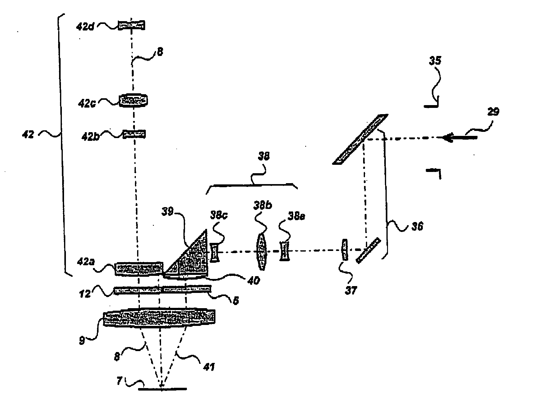
[0052] According to FIG. 7 and FIG. 8, the illumination light 29 entering from the light attachment 35 of the incident light fluorescence stereo microscope body 43 is deflected through the excitation filter 5 via a light staircase 36, an illumination lens 37, a light zoom 38, and a stationary deflecting element 39 with a convex lens 40 fitted to it and is then guided as excitation beam path 41 through the objective 9 at an inclination approaching the stereo angle from the back toward the circular light spot 7 in the object plane. The stereoscopic observation beam path 8 proceeding from the fluorescing object travels back via the objective 9 through two blocking filters 12 into the observation zoom 42 of the incident light fluorescence stereo microscope body 43 and continues to the observing tube 15. The light zoom 38 is connected to the observation zoom 42 by a suitable coupling element 44 in such a way that the illumination ratios in the excitation beam path 41 are correspondingly ...


PUM


Abstract

The invention is directed to a stereo microscope which is suitable particularly for observing fluorescence with incident light. Particularly advantageous fluorescence excitation is achieved when the illumination beam path has a zoom system by which an illumination is achieved that is adapted to the zoom factor of the observation beam path.

Description

CROSS-REFERENCE TO RELATED APPLICATION [0001] This application claims priority of German Application No. 103 55 523.4, filed Nov. 21, 2004, the complete disclosure of which is hereby incorporated by reference. BACKGROUND OF THE INVENTION [0002] a) Field of the Invention [0003] The invention is directed to a stereo microscope which is suitable particularly for fluorescence observation with incident light. [0004] b) Description of the Related Art [0005] The use of fluorescence contrast in stereo microscopy has become increasingly important in recent years because of new goals for applications in biology, medicine, science and technology. One example of such applications is the use of the GFP (Green Fluorescent Protein) fluorochrome in microbiology. [0006] Known equipment for fluorescence microscopy with stereo microscopes is based on different principles: a) Equipment for External Oblique Incident Light Fluorescence Excitation with Lightguides and Focusing Attachments [0007] Equipmen...

Claims


Application Information

Patent Timeline
IPC IPC(8): G02B7/00G02B15/20G02B21/06G02B21/16G02B21/22
CPCG02B7/16G02B21/16G02B26/007G02B21/248G02B21/22
Inventor KLEINTEICH, LOTHARWINTEROT, JOHANNESKNOBLICH, JOHANNESKAUFHOLD, TOBIASOSTEN, GUENTER
Owner CARL ZEISS JENA GMBH
Why Eureka
Try Eureka