Proactive maintenance application

a technology of proactive maintenance and application, which is applied in the field of proactive maintenance prediction of public switched telephone network, can solve the problems of copper cable and wire deterioration, degrade service, and copper cable and wire suffering from ozone exposure, so as to reduce labor costs, improve revenue, and reduce redundant technician dispatch

Inactive Publication Date: 2005-05-26
BELLSOUTH INTPROP COR
View PDF26 Cites 19 Cited by
  • Summary
  • Abstract
  • Description
  • Claims
  • Application Information

AI Technical Summary

Benefits of technology

[0015] The Proactive Maintenance Application may be utilized for one or more functions. The Proactive Maintenance Application may monitor proactive maintenance, may assign proactive maintenance, and may track proactive maintenance. Because the Proactive Maintenance Application collects information from various departments and operations, one advantage is that the Proactive Maintenance Application provides a centralized database for proactive maintenance. The Proactive Maintenance Application may also be used to monitor the condition of equipment and facilities and predict what proactive maintenance should be performed. The Proactive Maintenance Application may also generate work orders describing the predicted proactive maintenance and then track the progress and completion of the work order. The Proactive Maintenance Application may even automatically update the centralized database so that management has a complete, accurate view of equipment and facilities.
[0016] The Proactive Maintenance Application may also be utilized to assign proactive maintenance in bulk. Bulk repairs reduce labor costs and improve revenue. Because the Proactive Maintenance Application monitors information from many departments, the Proactive Maintenance Application can assign a single technician to perform many overlapping repairs. The Proactive Maintenance Application can even identify what specialized skills and equipment will be needed to complete a repair and, once identified, assign those technicians that have the needed skills and labor costs by reducing redundant technician dispatches. Bulk repairs also quickly provide more facilities for more customers and, thus, more revenue for the company.

Problems solved by technology

Yet these copper cables and wires are known to deteriorate and to degrade service.
Copper cable and wire suffers from exposure to ozone, summer heat, winter cold, and water.
Telephone service providers, however, are challenged when monitoring and tracking proactive maintenance procedures.
Other managers have a backlog of repairs and require more time to learn what lines are functioning.
This varied management style reduces the ability of telephone companies to execute a unified, customer service plan.
The manual environment also does not adequately prioritize proactive maintenance.
A manager may often have a backlog of proactive maintenance work order.
The manual environment too easily allows technician efforts to be mistakenly assigned to lower-priority repair work.
The manual environment also hampers bulk repair efforts.
Because the manual environment does not collect and track repair work, managers and technicians have little knowledge of other repair efforts.
The manual environment hinders managers from assigning and tracking bulk copper cable repairs to avoid unnecessary labor costs.
The manual environment also inadequately measures technician proficiency.
Although some technicians can repair many copper cables in a few hours, other technicians may not be as efficient and may require more time.
The manual environment cannot monitor what really matters to internal customers; that is, the actual number of copper cables repaired by the technician.
The manual environment, then, cannot monitor technician efficiency and cannot objectively measure technician performance.
The manual environment fails to objectively reward technicians for their actual efforts.

Method used


Image

  • Proactive maintenance application
  • Proactive maintenance application
  • Proactive maintenance application

Examples


example

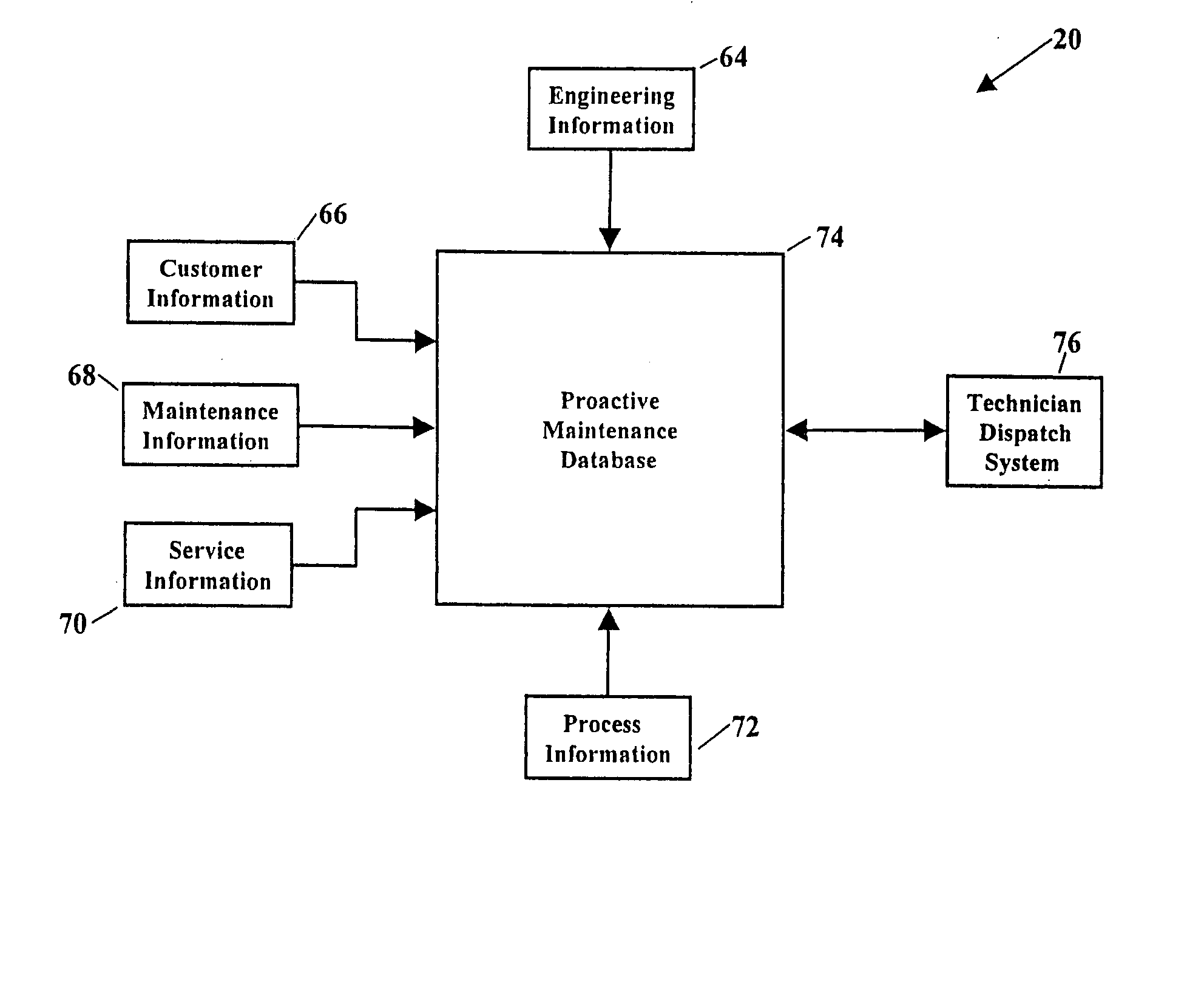
[0067] The Proactive Maintenance Application 20 is further illustrated by the following non-limiting example. FIG. 11 is a block diagram showing this particular non-limiting example is further configured for proactively maintaining the local loop (shown as reference numeral 78 in FIG. 4A). This non-limiting example is similar to that shown in FIG. 5, however, this example allows the Proactive Maintenance Application Database 74 to be accessed by several user groups. These user groups include a Proactive Analysis and Repair Center 142, a Facilities Analysis and Planning Center 144, a Service Advocate Center 146, a Work Management Center 148, an Address Facilities Inventory Group 150, and Outside Plant Engineers 152. These user groups have authority to access some or all information stored in the Proactive Maintenance Application Database 74. Some user groups may even have authority to alter information stored in the Proactive Maintenance Application Database 74. The Proactive Analysi...


PUM


Abstract

Methods and systems for proactively maintaining a telephone system local loop. One embodiment includes acquiring at least one type of information selected from information from a Dynamic Network Analyzer or information from a Loop Facilities and Control System. Another embodiment includes communicating with a communications network and acquiring at least one type of information selected from the group consisting of customer information associated with copper line pairs and service information associated with copper line pairs. Still another embodiment describes a system including software modules communicating with a communications network. Software modules include a Dynamic Network Analyzer module and a Loop Facilities and Control System module. A database interfaces with the Dynamic Network Analyzer module and with the Loop Facilities and Control System module. A processor is also included, and the processor is capable of processing information stored in the database and of generating proactive maintenance.

Description

CROSS-REFERENCE TO RELATED APPLICATIONS [0001] This application is a continuation of U.S. patent application Ser. No. 09 / 726,751 filed Nov. 30, 2000, which claims the benefit of U.S. Provisional Patent Application Number 60,212,207, filed Jun. 16, 2000, the contents of which are incorporated by reference herein in their entirety.NOTICE OF COPYRIGHT PROTECTION [0002] A portion of the disclosure of this patent document and its figures contain material subject to copyright protection. The copyright owner has no objection to the facsimile reproduction by anyone of the patent document or the patent disclosure, but otherwise reserves all copyrights whatsoever. BACKGROUND OF THE INVENTION [0003] 1. Field of the Invention [0004] This invention generally relates to methods for predicting proactive maintenance and, more particularly, to methods and systems for predicting proactive maintenance of the Public Switched Telephone Network. [0005] 2. Description of the Related Art [0006] Most reside...

Claims


Application Information

Patent Timeline
Patent Type & Authority Applications(United States)
IPC IPC(8): G06Q10/00H04M1/24H04M3/24H04M3/30H04Q3/00
CPCG06Q10/10H04M1/24H04M3/2254H04Q3/0087H04M3/30H04M2203/051H04M2203/056H04M3/247
Inventor BEAMON, ELIZABETH ANN
Owner BELLSOUTH INTPROP COR
Why Eureka
Try Eureka