Alkaline electrolyte fuel cells with improved hydrogen-oxygen supply system

a fuel cell and alkaline electrolyte technology, applied in electrochemical generators, cell components, cell component details, etc., can solve the problems of increased overvoltage at the anode, easy poisoning, and limited fuel supply to non-reactive constituents

Inactive Publication Date: 2005-05-26
ENER1
View PDF2 Cites 25 Cited by
  • Summary
  • Abstract
  • Description
  • Claims
  • Application Information

AI Technical Summary

Benefits of technology

[0030] FIGS. 3(a), (b) and (c) show examples of gas supply periods, pauses and cycles of an aperiodic load based reactant flow supply arrange

Problems solved by technology

The major disadvantage of an AFC is that it is easily poisoned.
Thus, the fuel supply is limited to non-reactive constituents except for hydrogen.
In addition, the decrease in catalytic activity results in increased over-voltage at the anode and hence the cell is much less efficient adding significantly to the operating costs.
Even the small amount of CO2 in the air can affect the cell's operation, making it necessary to purify both the hydrogen and oxygen used in the cell.
This purification process is costly.
Susceptibility to poisoning also affects the cell's lifetime (the amount of time before it must be replaced), further adding to its cost.
High fuel cell stack temperature levels can cause corrosion of the electrochemical components and degradation of volt-amp characteristics of the FCS.
Another problem with present designs is the oxygen supply system which is known to determine the reliability of the AFC.
This condition causes intensive water evaporation at the oxygen entry area to the cathode and matrix, which in turn, leads to increases in local electrolyte concentration in the cathode, matrix pores, and anode.
This also accelerates the rate of localized matrix corrosion.
Resulting formation of large pores and low electrolyte capillary pressure in localized matrix zones may fail to prevent direct mixing of hydrogen and oxygen within low operational times, such as 300-500 hrs.
This is due, in part, to the acceleration in

Method used


Image

  • Alkaline electrolyte fuel cells with improved hydrogen-oxygen supply system
  • Alkaline electrolyte fuel cells with improved hydrogen-oxygen supply system
  • Alkaline electrolyte fuel cells with improved hydrogen-oxygen supply system

Examples


example

[0074] It should be understood that the examples and embodiments described herein are for illustrative purposes only and that various modifications or changes in light thereof will be suggested to persons skilled in the art and are to be included within the spirit and purview of this application. The invention can take other specific forms without departing from the spirit or essential attributes thereof.

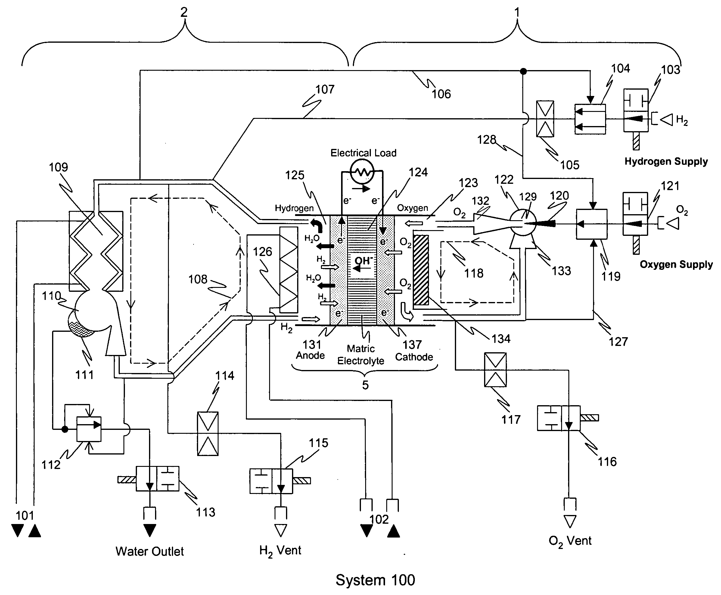
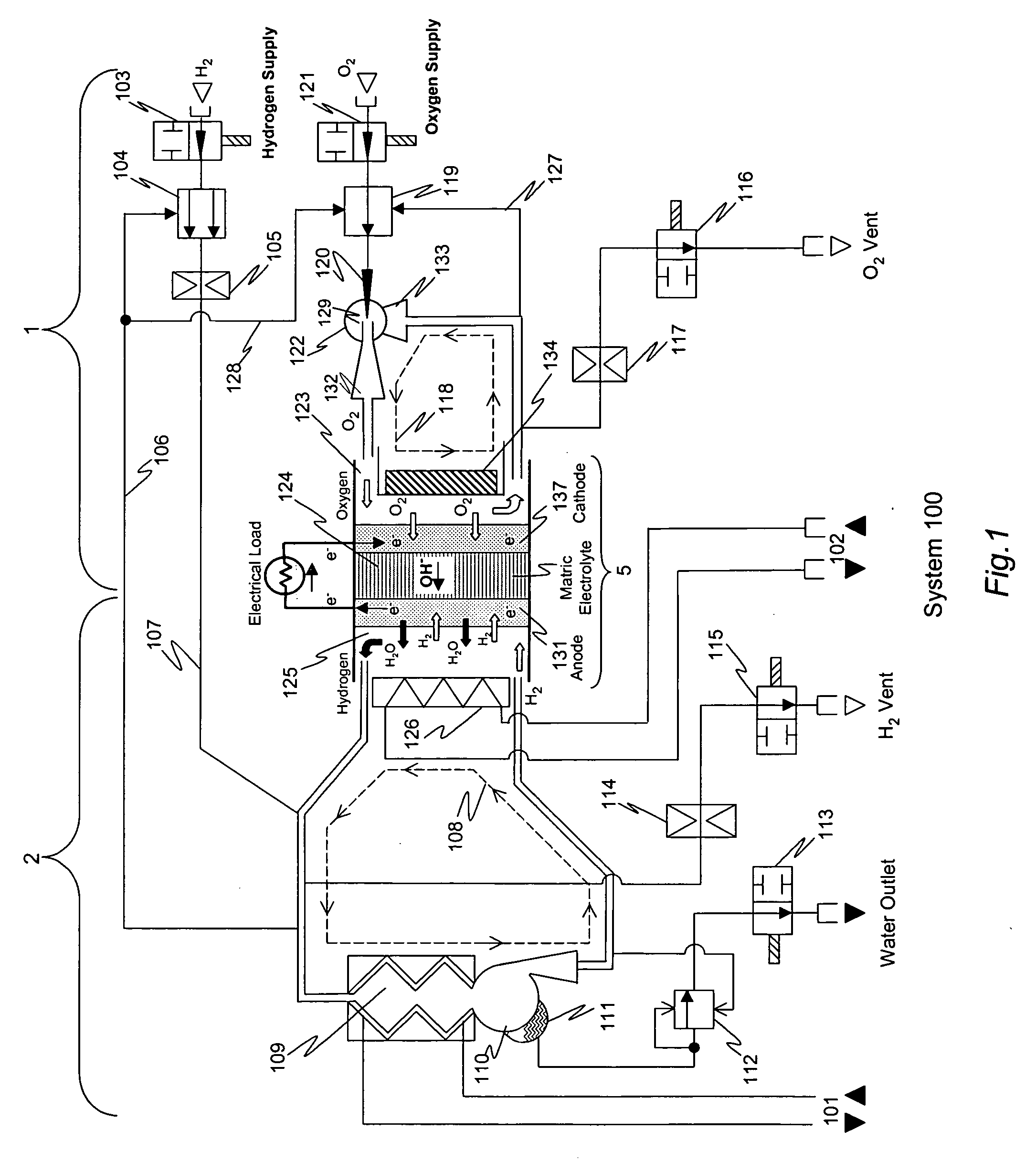
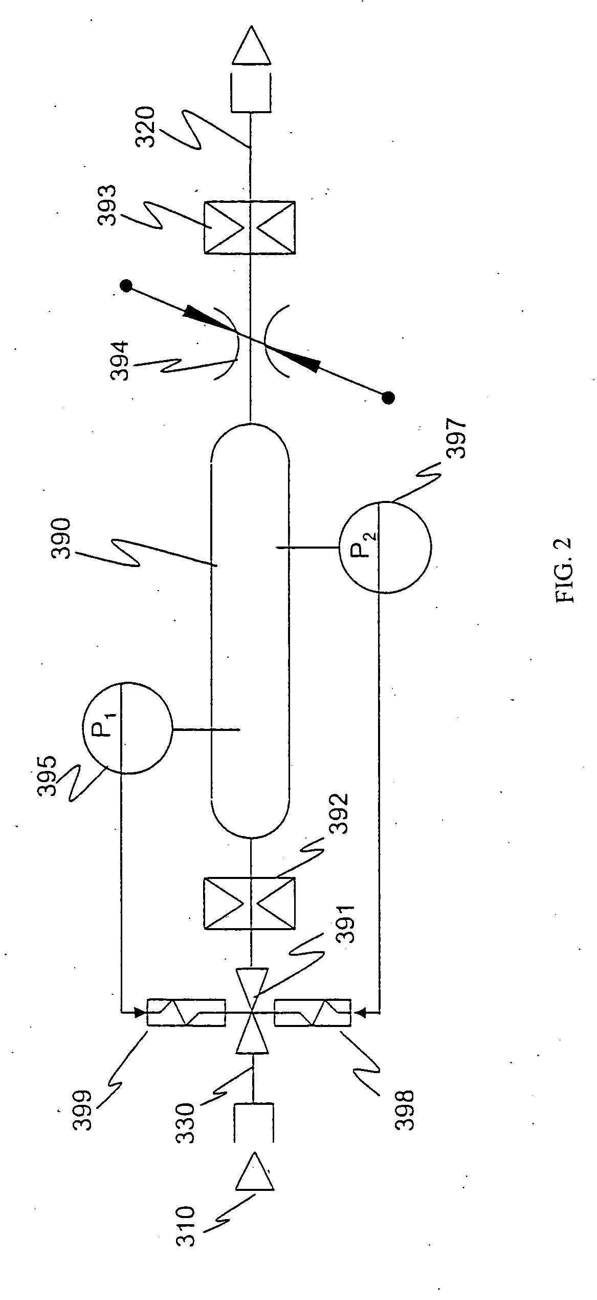
[0075] The invention was implemented as a prototype AFC stack comprising 96 cells. The size of the cells in the stack was approximately 200 cm2. The stack was operated and monitored for more than 5000 hours. Principal operating parameters and selected test data are shown in Table 2 below. During the testing process, the hydrogen supply system employed a two-position type regulator and throttle as described above to established pressure pulses in the hydrogen gas supply performed steadily over the entire range of external loads for which the system was designed to be (0-7.5 kW). Dur...


PUM


Abstract

A recirculating hydrogen-oxygen alkaline fuel-cell (AFC) includes an alkaline matrix electrolyte interposed between a porous anode and porous cathode, and an oxygen flow network in fluid connection with the porous cathode. The oxygen flow network has an input portion for supplying oxygen and an output portion for removing oxygen and reaction products after electrochemical reaction. A hydrogen flow network is in fluid connection with the porous anode. The hydrogen network has an input portion for supplying hydrogen and an output portion for removing hydrogen and reaction products after electrochemical reaction. At least one of the oxygen flow network and the hydrogen flow network includes a feedback conduit to form a recirculation loop. The recirculation loop feeds back a portion of the hydrogen or oxygen flow after electrochemical reaction to the input portion.

Description

CROSS-REFERENCE TO RELATED APPLICATIONS [0001] This application claims the benefit of U.S. Provisional Application No. 60 / 524,951 entitled “ALKALINE ELECTROLYTE FUEL CELLS WITH IMPROVED HYDROGEN-OXYGEN SUPPLY SYSTEM” filed on Nov. 25, 2003, the entirety of which is incorporated herein by reference.FEDERALLY SPONSORED RESEARCH [0002] Not applicable. FIELD OF THE INVENTION [0003] The invention relates to hydrogen-oxygen fuel cell generators with alkaline electrolytes, and more specifically to improved hydrogen and oxygen supplies for these systems. BACKGROUND OF THE INVENTION [0004] Efficient operation of hydrogen-oxygen electrochemical generators, based on fuel cells of any type, requires maintenance of optimum pressures, temperature and water concentration on the anode and cathode in the face of wide variations in load demand. Such requirements apply to fuel cells having polymer, alkaline matrix, or circulating electrolyte systems. Dynamic systems are often used for removal of water...

Claims


Application Information

Patent Timeline
IPC IPC(8): H01M8/02H01M8/04H01M8/08
CPCH01M8/0291H01M8/04089H01M8/04097Y02E60/50H01M8/04164H01M8/083H01M8/04141H01M8/0289
Inventor GURIN, VICTORNOVAK, PETER
Owner ENER1
Why Eureka
Try Eureka