Magnetic carrier and two-component developer

Inactive Publication Date: 2005-05-26
CANON KK
View PDF3 Cites 19 Cited by
  • Summary
  • Abstract
  • Description
  • Claims
  • Application Information

AI Technical Summary

Benefits of technology

[0012] More specifically, an object of the present invention is to provide a magnetic carrier and a two-component developer which are not causative of image defects such as blank areas and promise high image density and superior dot reproducibility.
[0013] A further object of the prese

Problems solved by technology

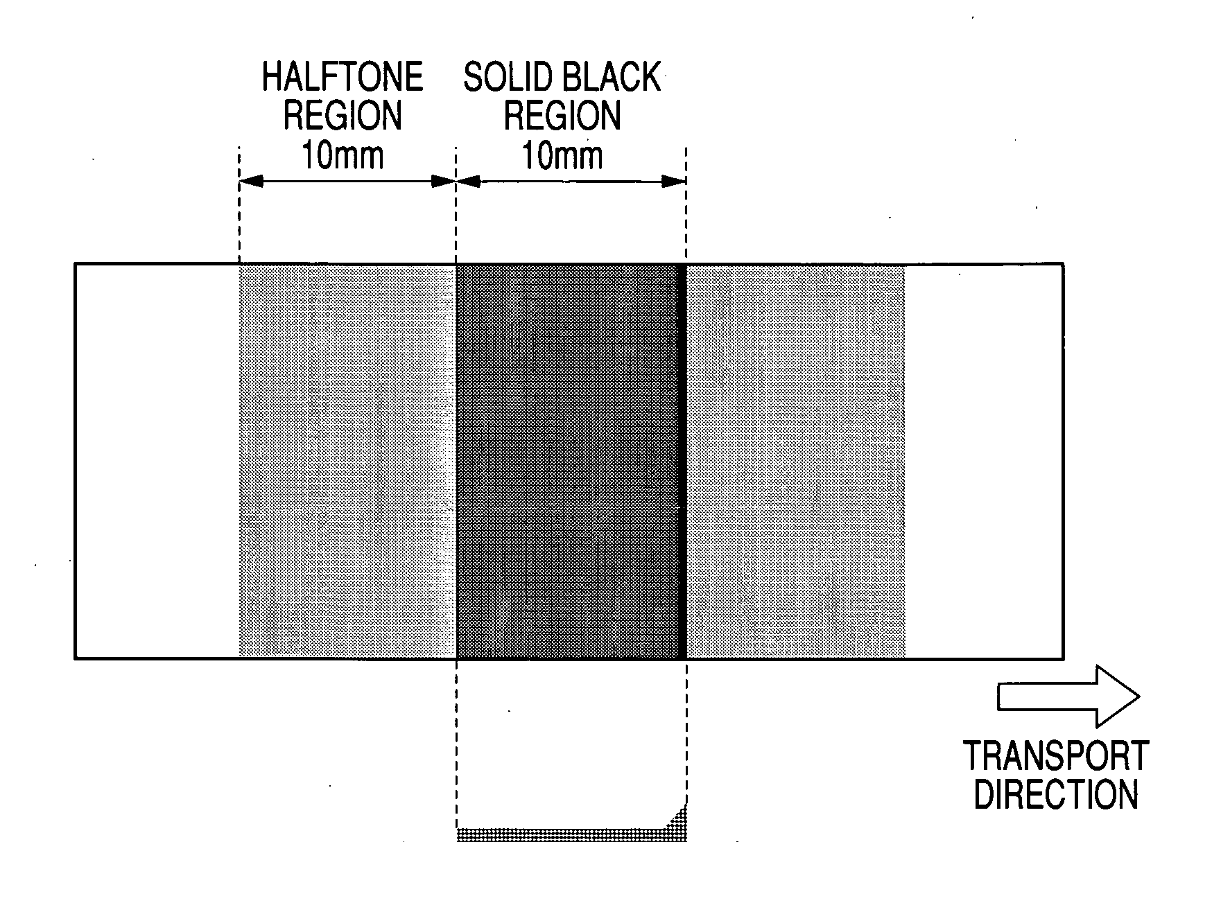
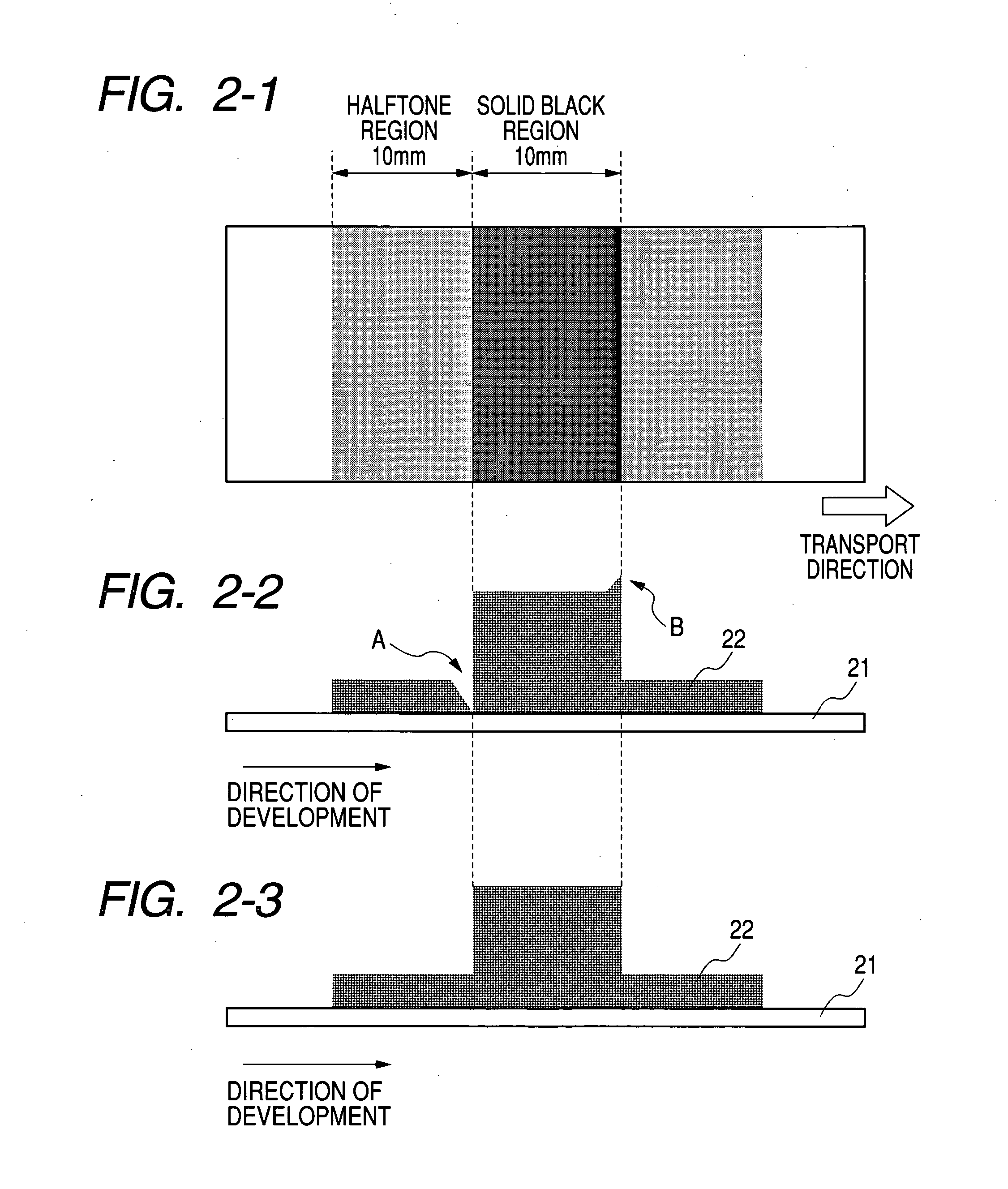
However, the carrier is made insulative by the resin coating and comes not to function as a development electrode at the time of development, thereby causing image defects such as called blank areas where an edge effect appears between halftone and solid black.
However, since ferrite particles are used as core particles, brush images of a developer magnetic brush tend to appear in the contact two-component development, and also the stress applied to the toner when low-consumption printing is continued may cause the toner to deteriorate, resulting in such a problem that it is difficult for the toner to come away from the carrier.
However, where the process speed has bee

Method used


Image

  • Magnetic carrier and two-component developer
  • Magnetic carrier and two-component developer
  • Magnetic carrier and two-component developer

Examples


production example 1

Coat Resin Production Example 1

[0284] 3 parts by weight of a methyl methacrylate macromer with a weight-average molecular weight of 5,000, having an ethylenically unsaturated group at one terminal, represented by the following Formula (8):

46 parts by weight of Exemplary Compound 1 having a structure represented by the following Formula (7):

and 51 parts by weight of methyl methacrylate were introduced into a four-necked flask provided with a reflux condenser, a thermometer, a nitrogen suction pipe and a stirrer of a grinding system, and then, 100 parts by weight of toluene, 100 parts by weight of methyl ethyl ketone and 2.4 parts by weight of azobizisovaleronitrile were further added thereto, and kept at 80° C. for 10 hours in a stream of nitrogen to obtain a solution (solid content: 35% by weight) of a graft copolymer (A) having a unit represented by the following Formula (9):

wherein a1, b1, c1 and d1 each independently represent an integer of 1 or more. The graft copolymer...

production example 2

Coat Resin Production Example 2

[0285] A graft copolymer (B) having the unit represented by the above Formula (9) was obtained in the same manner as in Coat Resin Production Example 1 except that the compound having the structure represented by the above Formula (7), the methyl methacrylate and the azobizisovaleronitrile were used in amounts changed to 164 parts by weight, 33 parts by weight and 3 parts by weight, respectively. The graft copolymer (B) had a weight-average molecular weight of 23,000 as measured by gel permeation chromatography (GPC). The graft copolymer (B) had Fcalc / Ccalc of 0.48.

production example 3

Coat Resin Production Example 3

[0286] A graft copolymer (C) having the unit represented by the above Formula (9) was obtained in the same manner as in Coat Resin Production Example 1 except that the compound having the structure represented by the above Formula (7) and the methyl methacrylate were used in amounts changed to 17 parts by weight and 90 parts by weight, respectively. The graft copolymer (C) had a weight-average molecular weight of 25,000 as measured by gel permeation chromatography (GPC). The graft copolymer (C) had Fcalc / Ccalc of 0.08.


PUM

PropertyMeasurementUnit
Fractionaaaaaaaaaa
Fractionaaaaaaaaaa
Fractionaaaaaaaaaa

Abstract

A magnetic carrier composed of carrier particles is provided in which each carrier particle has a carrier core including magnetic fine particles and a binder resin with the carrier core surface being coated with a coat material containing a coat resin. In the magnetic carrier, Fatom/Catom and (Fatom/Catom)/(Fcalc/Ccalc) are respectively in specific ranges, wherein Fatom and Catom represent respectively a fluorine element abundance ratio and a carbon element abundance ratio at the magnetic carrier particle surface, and Fcalc and Ccalc represent respectively a fluorine element abundance ratio and a carbon element abundance ratio which are calculable from the molecular structure of the coat resin. In addition, a two-component developer is provoded including the magnetic carrier and a toner having a specific contact angle against water.

Description

BACKGROUND OF THE INVENTION [0001] 1. Field of the Invention [0002] This invention relates to a two-component developer used in electrophotography, electrostatic recording and electrostatic printing, and a magnetic carrier included in the developer. [0003] 2. Related Background Art [0004] Conventionally, in image forming apparatus making use of electrophotography, such as printers and copying machines, two-component developers containing toners and carriers are preferably used from the viewpoint of image quality, running performance and high-speed adaptability. As a method of performing development using such two-component developers, in order to secure sufficient image density and enhance fine-line reproducibility, a method is employed in which development is performed in the state a magnetic brush of a developer is brought into contact with a photosensitive member, the peripheral speed of a developing sleeve is made higher than the peripheral speed of the photosensitive member, an...

Claims


Application Information

Patent Timeline
IPC IPC(8): G03G9/08G03G9/087G03G9/097G03G9/113
CPCG03G9/0804G03G9/081G03G9/0815G03G9/08722G03G9/09708G03G9/08777G03G9/08795G03G9/08797G03G9/08775
Inventor FUJIKAWA, HIROYUKIITAKURA, TAKAYUKIKOBORI, TAKAKUNIISHIGAMI, KOHSUGAHARA, NOBUYOSHIBABA, YOSHINOBUTANIKAWA, HIROHIDE
Owner CANON KK
Why Eureka
Try Eureka