Hydrogen gas station, fuel cell system, and hydrogen gas rate accounting device

a hydrogen gas rate and accounting device technology, applied in the direction of combustible gas production, process and machine control, fluid pressure control, etc., can solve the problems of substantial start energy loss and time loss, insufficient hydrogen generation efficiency of the fuel cell supply system, and reduced hydrogen generation efficiency of the reformer. , to achieve the effect of efficient utilization of off gas

Inactive Publication Date: 2005-06-02
PANASONIC CORP
View PDF1 Cites 14 Cited by
  • Summary
  • Abstract
  • Description
  • Claims
  • Application Information

AI Technical Summary

Benefits of technology

[0016] The present invention has been developed under the circumstances, and an object of the present invention is to provide a hydrogen gas station and a fuel cell system which are configured to recover an off gas containing hydrogen unconsumed in a plurality of fuel cells and exhausted from fuel gas outlets of the plurality of fuel cells to efficiently utilize the off gas.
[0017] Another object of the present invention is to provide a hydrogen gas rate accounting device capable of appropriately carrying out hydrogen gas rate accounting by estimating value of the off gas exhausted from the fuel gas outlets of the plurality of fuel cells.

Problems solved by technology

In actuality, however, infrastructures of the supply system of hydrogen used as the fuel for the fuel cell are not adequately equipped.
Typically, the reforming reaction (endothermic reaction) for generating hydrogen in the reformer is carried out at a high temperature of approximately 700° C. The change of operating conditions (e.g., temperature) of the reformer depending on the constant variation in the amount of hydrogen required causes a substantial heat loss, thereby resulting in reduction of hydrogen generation efficiency in the reformer.
For example, if the temperature of the reformer is lowered to a room temperature and then increased up to 700° C., such a temperature increasing operation may cause substantial start energy loss and time loss.
In other words, the fuel cell system of the first prior art is undesirable to the home fuel cell system which is required to constantly vary the amount of electric power, because of difficulty in improving energy utilization efficiency of the reformer equipped in the fuel cell system.
However, the efficient use of the off gas exhausted from the anode of the fuel cell and its recovery method are not achieved in the hydrogen supply system of the third prior art.
In addition, in the fuel cell system of the second prior art, recovery of the off gas using hydrogen absorbing alloy is suggested, but the efficient use of the off gas is not achieved as in the hydrogen supply system of the third prior art.

Method used


Image

  • Hydrogen gas station, fuel cell system, and hydrogen gas rate accounting device
  • Hydrogen gas station, fuel cell system, and hydrogen gas rate accounting device
  • Hydrogen gas station, fuel cell system, and hydrogen gas rate accounting device

Examples


embodiment 1

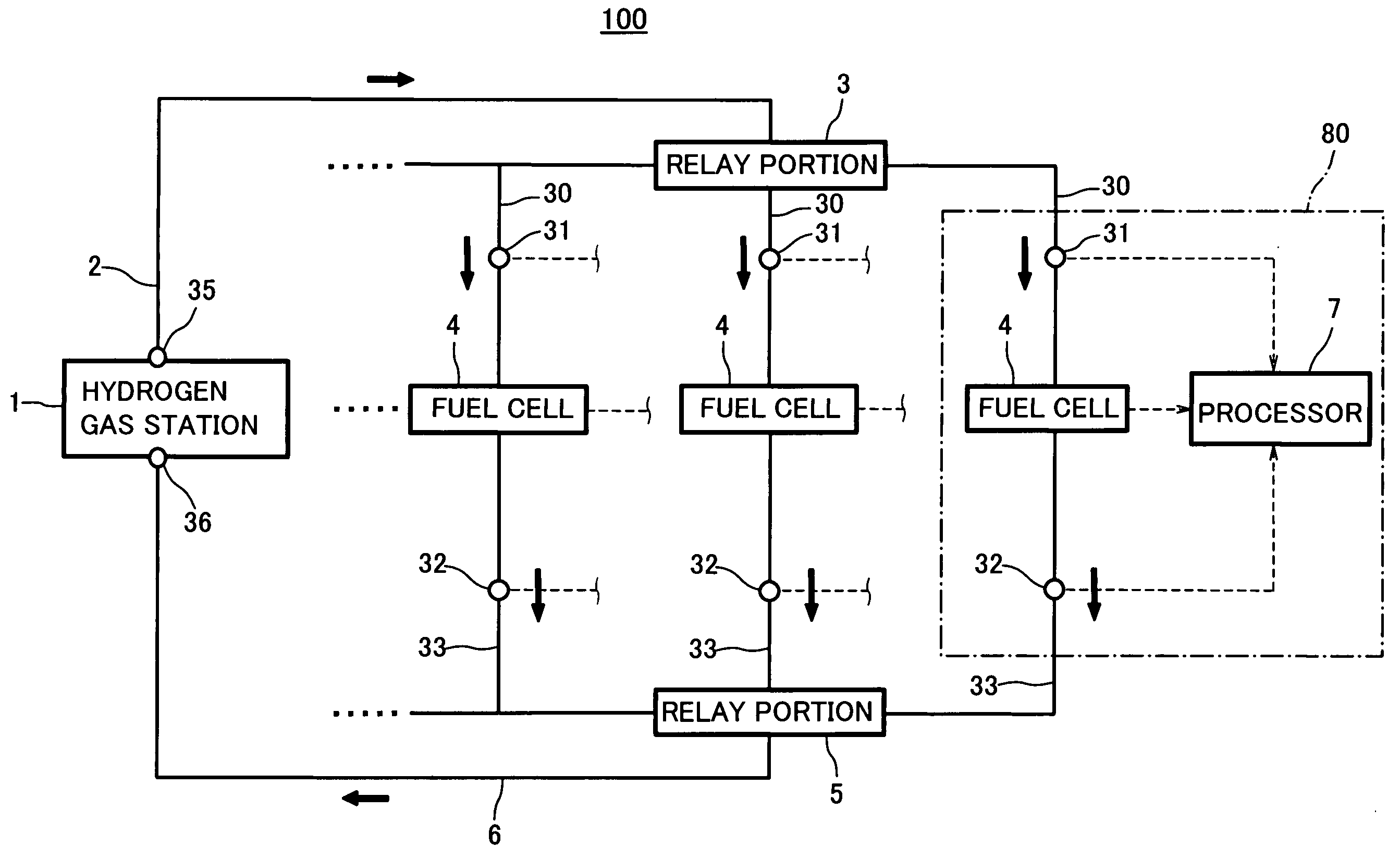
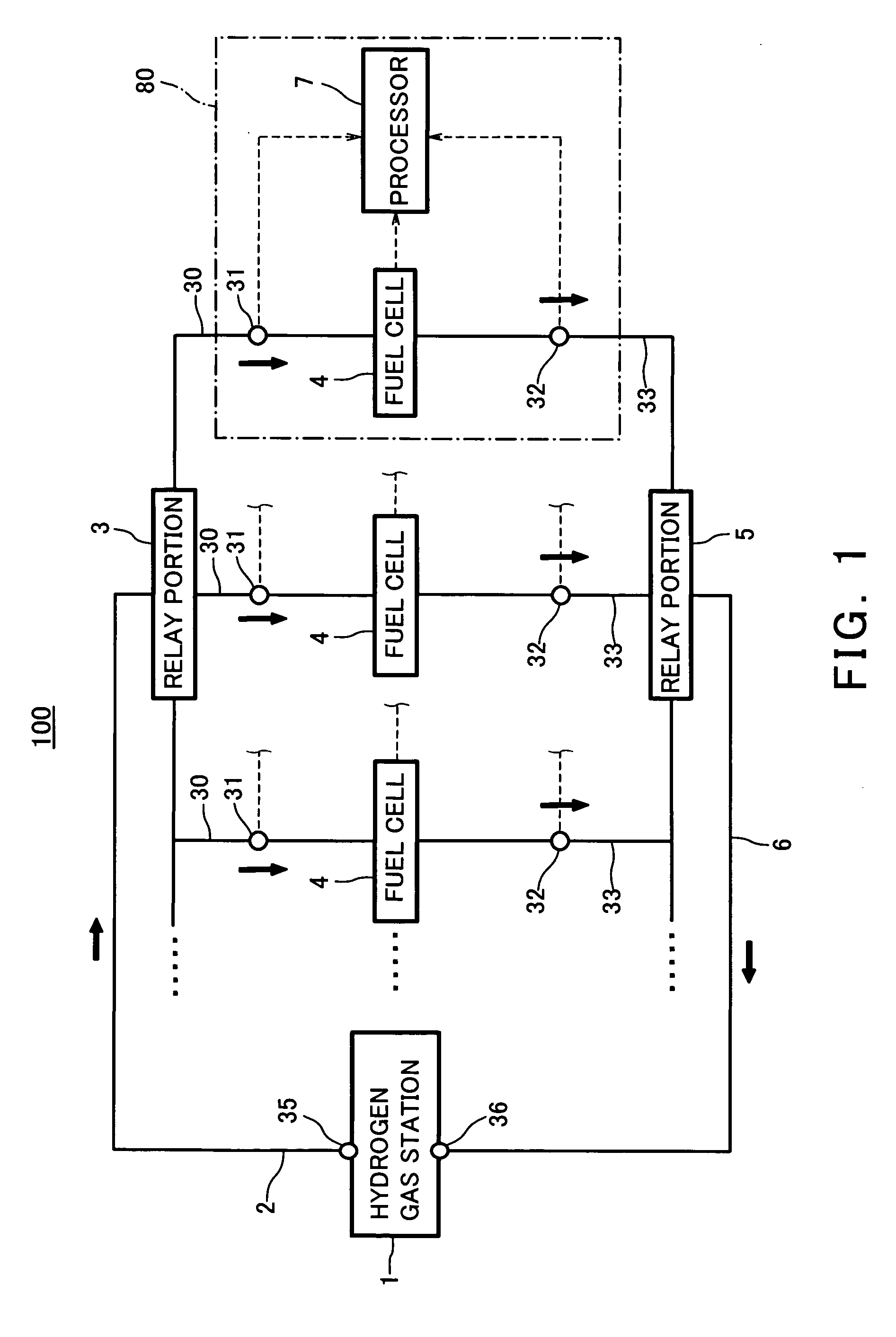
[0067]FIG. 1 is a view showing a construction of a distributed fuel cell system 100 according to a first embodiment of the present invention. The distributed fuel cell system 100 (hereinafter simply referred to as a fuel cell system 100) according to the first embodiment mainly comprises a hydrogen gas station 1, and a plurality of fuel cells 4 which are gas consumption equipment. The hydrogen gas station 1 is configured to generate a hydrogen-rich reformed gas and to supply the hydrogen-rich reformed gas to the plurality of fuel cells 4. Each fuel cell 4 is configured to consume the reformed gas (hydrogen) to generate electric power and heat. An internal construction of the hydrogen gas station 1 will be described in detail later.

[0068] The hydrogen supply system of the fuel cell system 100 includes a gas supply main pipe (gas supply pipe ) 2, a plurality of gas supply sub-pipes (gas supply pipes) 30, and a supply relay portion 3. A gas supply port 35 of the hydrogen gas station 1...

embodiment 2

[0109] In the first embodiment, the off gas exhausted from the fuel gas outlet of each fuel cell 4 is returned to the hydrogen gas station 1 and used therein to generate the reformed gas. How to utilize the off gas is not intended to be limited to this.

[0110] In a second embodiment, the off gas is utilized as a heat source of heat energy which is deficient in the fuel cell 4. For example, as shown in FIG. 5, each fuel cell 4 may be equipped with an off gas treatment device 20 capable of combusting part or all of the off gas to generate a high-temperature combustion gas which can re-heat the hot water generated in power generation operation of the fuel cell 4 by heat exchange.

[0111]FIG. 5 shows an embodiment in which the off gas is utilized by using the off gas treatment device 20 and a hot water tank 19. The construction and operation in FIG. 5 are substantially identical to those of the first embodiment except for how to utilize the off gas, and description of the construction an...

embodiment 3

[0120] In a first embodiment, the gas supply sub-pipe 30 and the gas recovery sub-pipe 33 are equipped as separate infrastructures. Likewise, the gas supply main pipe 2 and the gas recovery main pipe 6 are installed as separate infrastructures.

[0121] However, when the piping is carried out by separately providing the gas supply sub-pipe 30 and the gas recovery sub-pipe 33, this may negatively affect the piping drawing, because of the presence of two kinds of pipes, i.e., the supply pipe and the recovery pipe in each gas consumption equipment.

[0122] In order to substantially solve the problem associated with the piping drawing, in the third embodiment, the gas supply sub-pipe 30 and the gas recovery sub-pipe 33 are integral with each other.

[0123]FIG. 3 is a view showing a pipe construction in which the gas supply sub-pipe 30 and the gas recovery sub-pipe 33 are integral with each other.

[0124] As can be seen from FIG. 3, an integral pipe 60 formed by the gas supply sub-pipe 30 and...


PUM

PropertyMeasurementUnit
temperatureaaaaaaaaaa
electric poweraaaaaaaaaa
pressureaaaaaaaaaa

Abstract

A hydrogen gas station is disclosed comprising, a reformer configured to generate a hydrogen-rich reformed gas through reforming reaction of an organic compound, a gas supply port configured to communicate with a gas supply pipe to supply the reformed gas to a plurality of fuel cells, and a gas recovery port configured to communicate with a gas recovery pipe to receive an off gas containing hydrogen unconsumed from the fuel cells, the hydrogen gas station being configured to consume the off gas.

Description

BACKGROUND OF THE INVENTION [0001] 1. Field of the Invention [0002] The present invention relates to a hydrogen gas station, a fuel cell system, and a hydrogen gas rate accounting device. More particularly, the present invention relates to a fuel cell system comprising a hydrogen gas station configured to generate a hydrogen-rich reformed gas through reforming reaction of an organic compound, and a plurality of fuel cells configured to consume the reformed gas to generate electric power. [0003] 2. Description of the Related Art [0004] A fuel cell configured to generate electric power and heat from hydrogen as a fuel is capable of converting fuel energy into effective electric energy and heat energy with high conversion efficiency. For this reason, a fuel cell system is capable of inhibiting the amount of emission of carbon dioxide because of the high conversion efficiency, and is therefore expected to reduce the carbon dioxide which may be a cause of global warming. [0005] In actual...

Claims


Application Information

Patent Timeline
Patent Type & Authority Applications(United States)
IPC IPC(8): C01B3/32C10J1/00H01M8/04H01M8/06H01M8/24
CPCC01B3/32Y02E60/50C01B2203/0227C01B2203/0283C01B2203/044C01B2203/047C01B2203/066C01B2203/0827C01B2203/148H01M8/04014H01M8/04022H01M8/04134H01M8/04201H01M8/04223H01M8/04388H01M8/04402H01M8/04462H01M8/04753H01M8/04992H01M8/0618H01M8/249Y02E60/34C01B2203/0205H01M8/04228
Inventor UKAI, KUNIHIROTAGUCHI, KIYOSHIWAKITA, HIDENOBUFUJIHARA, SEIJIKANI, YUKIMUNE
Owner PANASONIC CORP
Why Eureka
Try Eureka