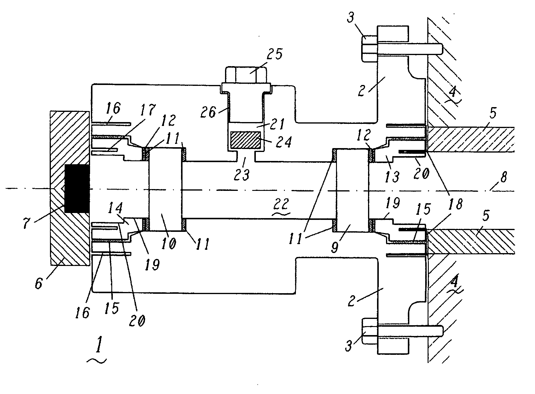
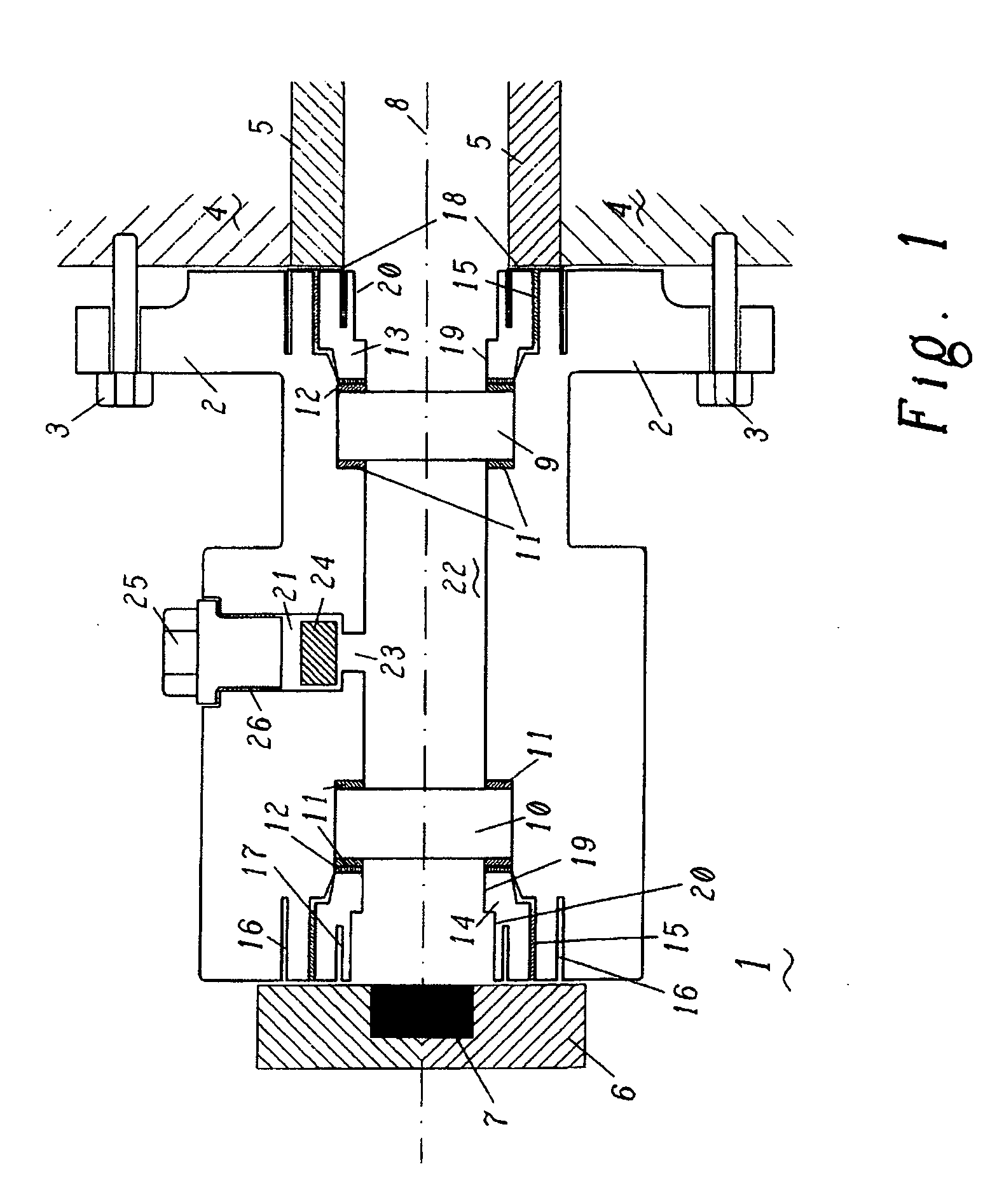
[0008] An exemplary flange in accordance with principles of the present invention is distinguished by the fact that two panes, which delimit a sealed intermediate space in the bore, are arranged one behind the other with respect to the
optical axis, exemplarily parallel to one another and perpendicular to the
optical axis, and that means for dehumidifying the sealed intermediate space are provided. Arranging two panes one behind the other has the
advantage of creating a redundant
system. In other words, the presence of two panes one behind the other results in increased safety, since each pane alone is advantageously able to withstand the entire
temperature difference and
pressure difference between the outside environment and the interior of the observation tube. Therefore, a defect at one of the two panes does not immediately lead to failure of the gas turbine (which is inevitable if there is open connection between the
combustion chamber and the outside environment), since the second pane can immediately take over the entire function of the first pane all on its own. Arranging two panes one behind the other presents problems insofar as humid air which may be enclosed in the intermediate space between the two panes has the tendency to condense on the cold pane, i.e. on the pane facing the observation means, above a certain
humidity level.
Fogging of this pane makes it difficult if not impossible to observe the flame using the observation means, since the
optical path is significantly impeded and therefore the measurement is distorted. According to the invention, this problem is solved by the provision of means for dehumidifying the intermediate space between the two panes. This can be achieved, for example, by the application of a vacuum. However, applying a vacuum has the drawback that the intermediate space between the two panes has to be extremely well sealed, since otherwise the vacuum cannot be ensured in the long term. In addition, under the standard pressure and temperature loads when using a flange of this type at a gas turbine, complete leaktightness of the intermediate space can only be ensured with very great difficulty, and accordingly a flange with an evacuated intermediate space has to be exchanged at frequent intervals, since evacuation in situ is scarcely possible. The continuous dehumidification of this intermediate space by dehumidification means of another type therefore prove to be simpler and more expedient, since maintenance of dehumidification means of this type is significantly simpler compared to when this region is evacuated. In particular, it is not generally necessary in this case for the entire flange to be exchanged, but rather only the dehumidification means have to be exchanged.
[0010] According to a further exemplary embodiment of the invention, the dehumidification means are arranged in such a manner in the flange that they can be inserted, exchanged and / or removed from the outer side of the flange, remote from the intermediate space. This arrangement of, for example, a
drying cartridge in the flange allows these dehumidification means to be exchanged without one of the two panes positioned one behind the other having to be removed from the flange. This makes maintenance of the flange particularly simple and efficient. In this case, the procedure is preferably such that there is at least one cavity, which is arranged to the side of the intermediate space with respect to the optical axis, for the dehumidification means, which cavity is in communication with the intermediate space, this communication being ensured in particular by means of at least one opening between the cavity and the intermediate space. This arrangement allows simple
accessibility from the side of the flange (substantially from the radial side with respect to the optical axis) without the
optical path being disrupted by the presence of the dehumidification means. Also preferably, the
accessibility to the dehumidification means is ensured by the fact that the flange has at least one hole which is arranged substantially perpendicular to the optical axis, is in communication with the intermediate space via at least one opening, provides a cavity for receiving the means and can be sealed off with respect to the outer side of the flange by means of closure means, in particular in the form of a sealing screw. The hole may have any desired cross section, but is advantageously of cylindrical configuration (in which case the
diameter is particularly preferably reduced just in front of the intermediate space, so that the
cartridge is held in the region with a large
diameter without dropping into the intermediate space), and is provided with an internal
screw thread in
its region remote from the intermediate space, so that, for example, a sealing screw (if appropriate provided with sealing rings) allows simple sealing of this hole after the
drying means have been inserted.
[0011] A further exemplary embodiment of the present invention is distinguished by the fact that the observation-side pane can be inserted, exchanged and / or removed from the observation-side end of the flange, and / or that the flame-side pane can be inserted, exchanged and / or removed from the flame-side end of the flange. This simple way of exchanging the panes from the respective side likewise ensures simple, low-cost maintenance of the observation flange. For example, the panes can simply be removed and replaced or cleaned in the event of fracture or in the event of them becoming dirty, respectively. In this context, it can be particularly advantageous for the mechanical configuration of the exchangeability to be identical in form from both sides, so that both the two panes and their securing means in the flange are identical, meaning that the number of different parts is minimized. The securing means used for the panes are advantageously grub screws with a central bore, i.e. at least one of the panes is held in an internal
screw thread arranged in the flange from the side remote from the intermediate space by means of at least one grub screw with an external
screw thread and with an axial hole. Moreover, in this context it has proven advantageous to provide second means, allowing the grub screw to be fixed with respect to its rotation in the internal screw thread. This is in order to prevent the grub screws from coming loose during operation under the vibrations which occur in
gas turbines, which can cause the leaktightness of the intermediate space to decrease on account of the loosening of the pressure on the plates. It is usual for the leaktightness on the side of the panes facing the intermediate space to be ensured by sealing rings (O rings). Sealing rings may also be arranged on the side facing the grub screw, if appropriate in combination with a
washer.
[0012] An exemplary embodiment of the grub screw is distinguished by the fact that it, on the side remote from the pane, has at least one bore, in particular in the form of a
blind hole, which is arranged substantially parallel to and laterally offset from the optical axis, and that the flange, at the corresponding end side, has a bore, in particular in the form of a
blind hole, which runs substantially parallel to the bore and is arranged axially outside the internal screw thread with respect to the optical axis, it being possible for the grub screw to be fixed by means of a securing clip which projects into the two bores. This is a simple, readily realizable embodiment of the second fixing means. The securing clip, which can easily be realized, for example, by a U-shaped wire, is in this way fixed in a simple and to a certain extent automatic way by the flange being secured to the housing and / or observation tube on the
combustion chamber side and / or by the fitting of an observation means to the outer side.

