Photo-electric conversion cell and array, and photo-electric generation system

a photoelectric generation system and photoelectric conversion technology, applied in the direction of photovoltaics, electrical devices, semiconductor devices, etc., can solve the problems of increasing the material cost of the connection electrode, reducing the connection strength, and difficult to handle the connection electrode, so as to improve the economic merit, improve and collect efficiently without reducing the efficiency of photovoltaic generation

Inactive Publication Date: 2005-06-02
KYOCERA CORP
View PDF6 Cites 104 Cited by
  • Summary
  • Abstract
  • Description
  • Claims
  • Application Information

AI Technical Summary

Benefits of technology

[0022] It is preferable that the collector electrode occupies a region that accounts for 10% to 40%, both inclusive, of an area of air spaces among the semiconductor particles. When this condition is satisfied, a current can be collected efficiently without reducing the efficiency of the photovoltaic generation caused by shadows, and the photo-electric conversion array becomes quite effective for practical use.
[0023] The collector electrode may be formed by subjecting electric conducting paste, made of heat-cured resin that contains an electric conducting material, to heat treatment. According to this forming method, the collector electrode can be formed easily, and can improve the economical merits markedly. The industrial value of the photo-electric conversion array is therefore quite high. In particular, because heat-cured resin is used, the collector electrode can be formed at low temperatures, which enables ITO, a suitable electric conducting material, to be used as the transparent electric conducting layer beneath the collector electrode.

Problems solved by technology

Also, turning over a photo-electric conversion cell reduces a connection strength during the process, which causes disconnection or the like.
In addition, the length of the connection electrode is extended, which not only makes the connection electrode difficult to handle, but also increases the material costs of the connection electrode.

Method used


Image

  • Photo-electric conversion cell and array, and photo-electric generation system
  • Photo-electric conversion cell and array, and photo-electric generation system
  • Photo-electric conversion cell and array, and photo-electric generation system

Examples


example 1-1

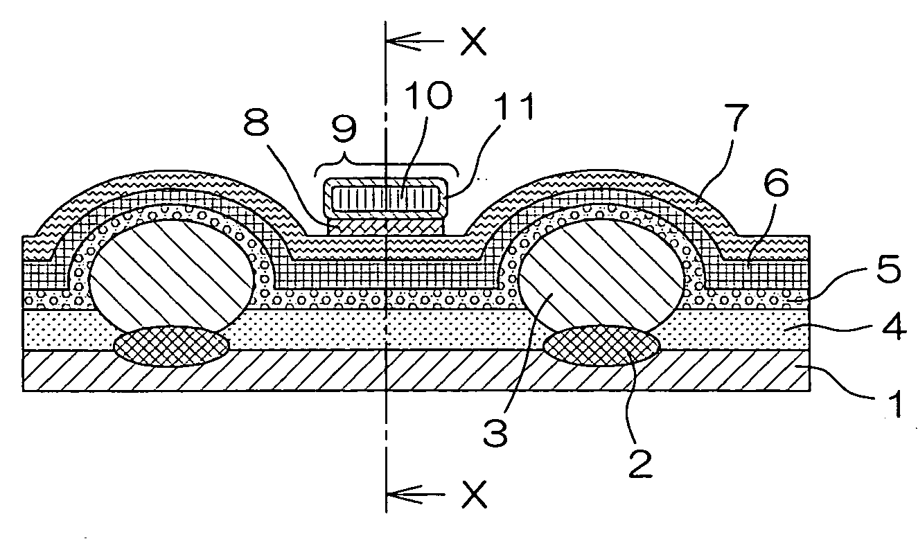
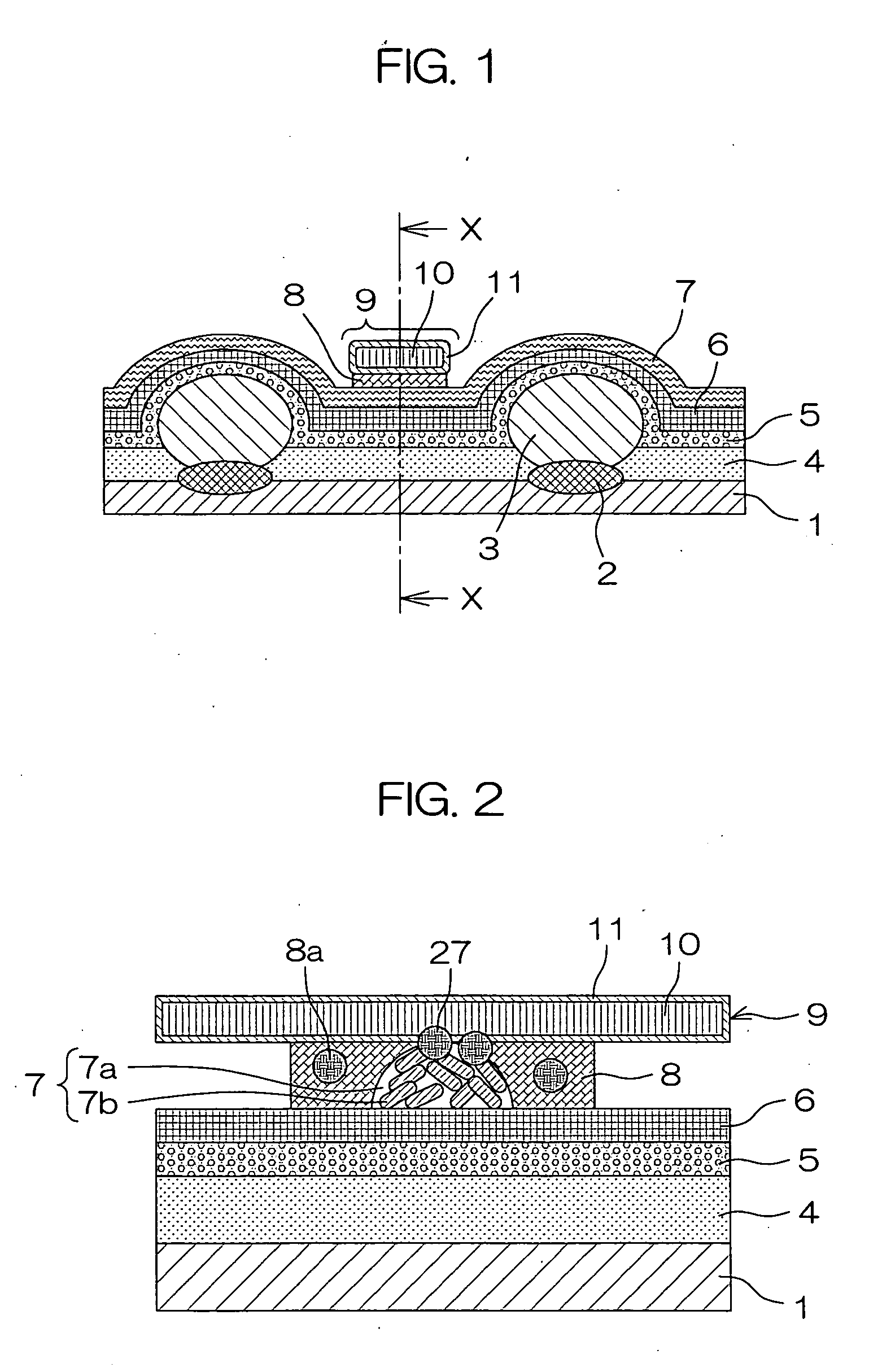
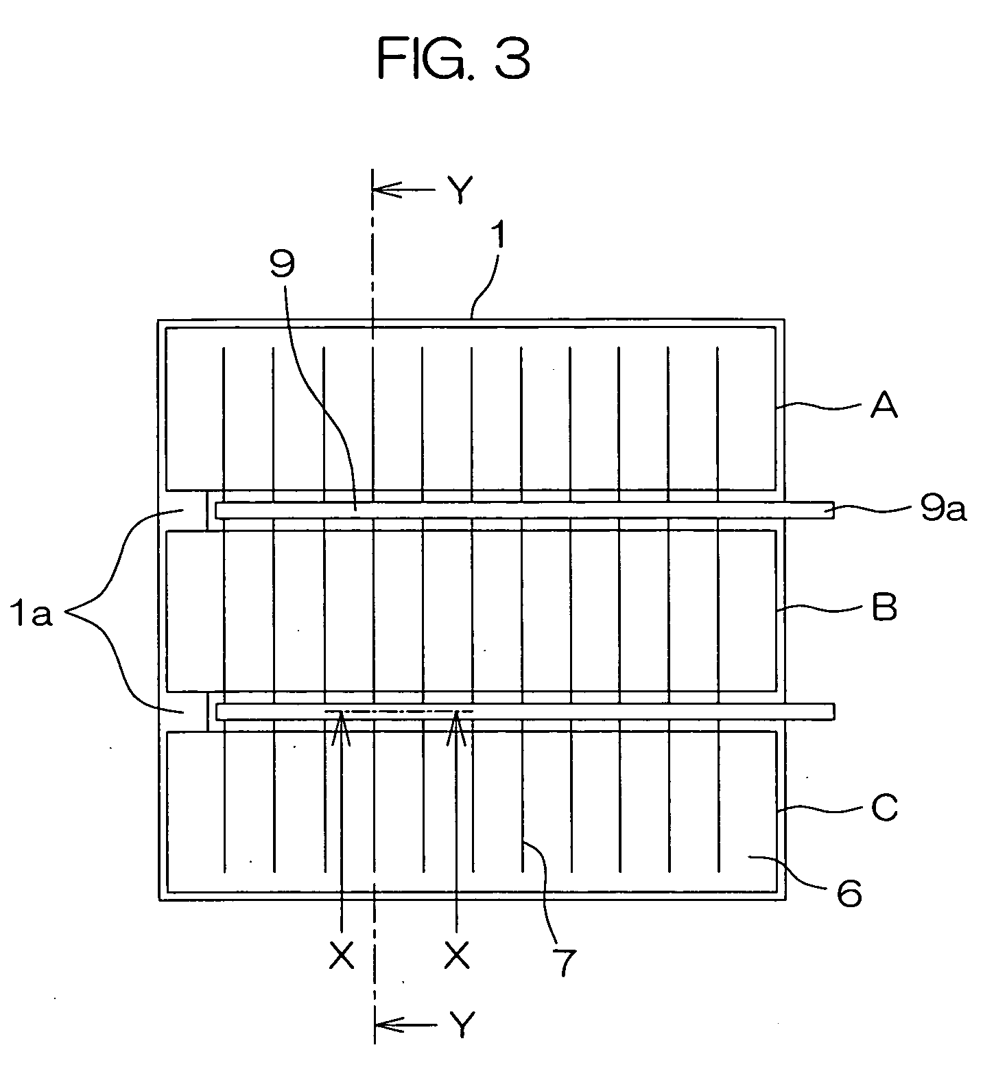
[0106] A substrate 1 was formed by forming aluminum alloy portions on the both surfaces of an aluminum alloy substrate or SUS 430 through cold rolling via a Ni foil. On the substrate 1 were randomly provided p-type silicon particles 3 while securing intervals from the bus bar attaching positions. Silicon particles 3 were bonded to the aluminum alloy by heating in atmosphere at or above 577° C., which is the eutectic temperature of aluminum and silicon. On top of this, an insulator, chiefly made of polyimide resin, was applied to continuously cover the side surface portion of the substrate 1 while end portions 1a were masked, followed by heating in atmosphere. The insulation layer 4 was thus formed. Subsequently, the top surfaces of the p-type silicon particles 3 were rinsed with a diluted aqueous solution of hydrofluoric acid (HF:pure water=1:100) for cleaning. A semiconductor layer 5, mixed crystals of n-type crystalline silicon and amorphous silicon, was formed above the silicon p...

example 1-2

[0110] The group of serially-connected cells of Example 1-1 was made into a module by the lamination processing in a vacuum laminating apparatus in the structure: glass substrate / EVA / cell / EVA / PET lamination sheet (back sheet), followed by crosslinking for 30 min. in an oven heated to 150° C. The crosslinking was performed to polymerize molecules of EVA. This module is referred to as Example 1-2. The output terminal was pulled to the back surface before the lamination processing, and pulled out through a take-off made in EVA and the back sheet.

example 1-3

[0111] The cell connection electrodes were formed from an electric-conducting adhesive agent. The electric-conducting adhesive agent, which was based on resin containing silver or other kinds of electric conducting powder, was adhered by heating and pressing at about 200° C. The rest of the fabrication was the same as that in Example 1-2.


PUM


Abstract

A photo-electric conversion array is formed by connecting photo-electric conversion cells in series. Each photo-electric conversion cell includes: a substrate, at least one main surface of which is made of a conductor layer; plural crystalline semiconductor particles provided on the conductor surface of the substrate; an insulation layer filled in clearances among the crystalline semiconductor particles; a transparent electric conducting layer provided above the plural crystalline semiconductor particles; a collector electrode, formed on the transparent electric conducting layer, to collect electricity from the transparent electric conducting layer. The substrate is provided with a substrate electrode portion at one end portion, through which the conductor surface of the substrate is exposed, and a connection electrode is formed by extending the collector electrode, so that the connection electrode in a given photo-electric conversion cell is connected to the substrate electrode portion in another photo-electric conversion cell. It is thus possible to provide a photo-electric conversion array capable of maintaining the reliability as to the adhesion strength, with a good outward appearance as well as excellent reliability and power generation efficiency.

Description

BACKGROUND OF THE INVENTION [0001] 1. Field of the Invention [0002] The present invention relates to a photo-electric conversion cell for use in photovoltaic generation or the like, comprising a substrate, at least one main surface of which is made of a conductor layer, crystalline semiconductor particles to perform photo-electric transfer, a transparent electric conducting layer to serve as the other electrode, and a collector electrode to collect a current from the transparent electric conducting layer. The invention also relates to a photo-electric conversion array comprising serially-connected photo-electric conversion cells and a photo-electric generation system. [0003] 2. Description of the Related Art [0004] In a case where photo-electric conversion cells are connected in series, the collector electrode of a given photo-electric conversion cell needs to be connected to the substrate electrode of an adjacent photo-electric conversion cell. For the electrode used for this conne...

Claims


Application Information

Patent Timeline
Patent Type & Authority Applications(United States)
IPC IPC(8): H01L31/00H01L31/062H01L31/113
CPCH01L31/035281H01L31/0508H01L31/03845Y02E10/50
Inventor SENTA, HIROFUMIKYODA, TAKESHIOKADA, KENICHIARIMUNE, HISAO
Owner KYOCERA CORP
Why Eureka
Try Eureka