
Organic electroluminescence element and manufacturing method thereof

a technology of electroluminescence element and manufacturing method, which is applied in the direction of discharge tube/lamp details, discharge tube luminescnet screen, organic semiconductor device, etc., can solve the problem of difficult to produce organic el element with a large area, difficult to effectively obtain blue light from the electrode, and limited electrode material, etc. problem, to achieve the effect of increasing the light energy taken out to the outsid

Inactive Publication Date: 2005-06-02
IDEMITSU KOSAN CO LTD
View PDF8 Cites 3 Cited by
  • Summary
  • Abstract
  • Description
  • Claims
  • Application Information

AI Technical Summary

Benefits of technology

The present invention relates to an organic EL element comprising an anode, a semiconductor layer, an organic light-emitting medium, and a cathode. The invention is characterized in that the second electrode is electrically connected to the semiconductor layer either by being in the same position as the first electrode or by being connected to the edge section of the semiconductor layer. This allows for the use of low-resistance opaque materials for both electrodes, resulting in increased light energy output. The second electrode can be connected to the semiconductor layer at multiple locations, and the electrically connected section can be made into a large area to prevent short-circuiting. The non-monocrystal materials used for the semiconductor layer can be selected from a variety of options, such as metal oxide non-degenerate semiconductors or conductive conjugate polymers. The band gap of the semiconductor layer should be held to 2.7 eV or higher to improve transparency and increase light energy output. The thickness of the semiconductor layer should be held within 1-700 nm to achieve the desired intensity and improve transparency.

Problems solved by technology

Consequently, with regard to the light transmittance of the electrode, there are problems in that the electrode material is limited to transparent material, such as indium tin oxide (ITO) or the blue light is difficult to be effectively obtained from the electrodes 201, 203.
More concretely, since making such monocrystal semiconductor material is not easy, it is difficult to produce an organic EL element with a large area.

Method used


Image

  • Organic electroluminescence element and manufacturing method thereof
  • Organic electroluminescence element and manufacturing method thereof
  • Organic electroluminescence element and manufacturing method thereof

Examples


first embodiment

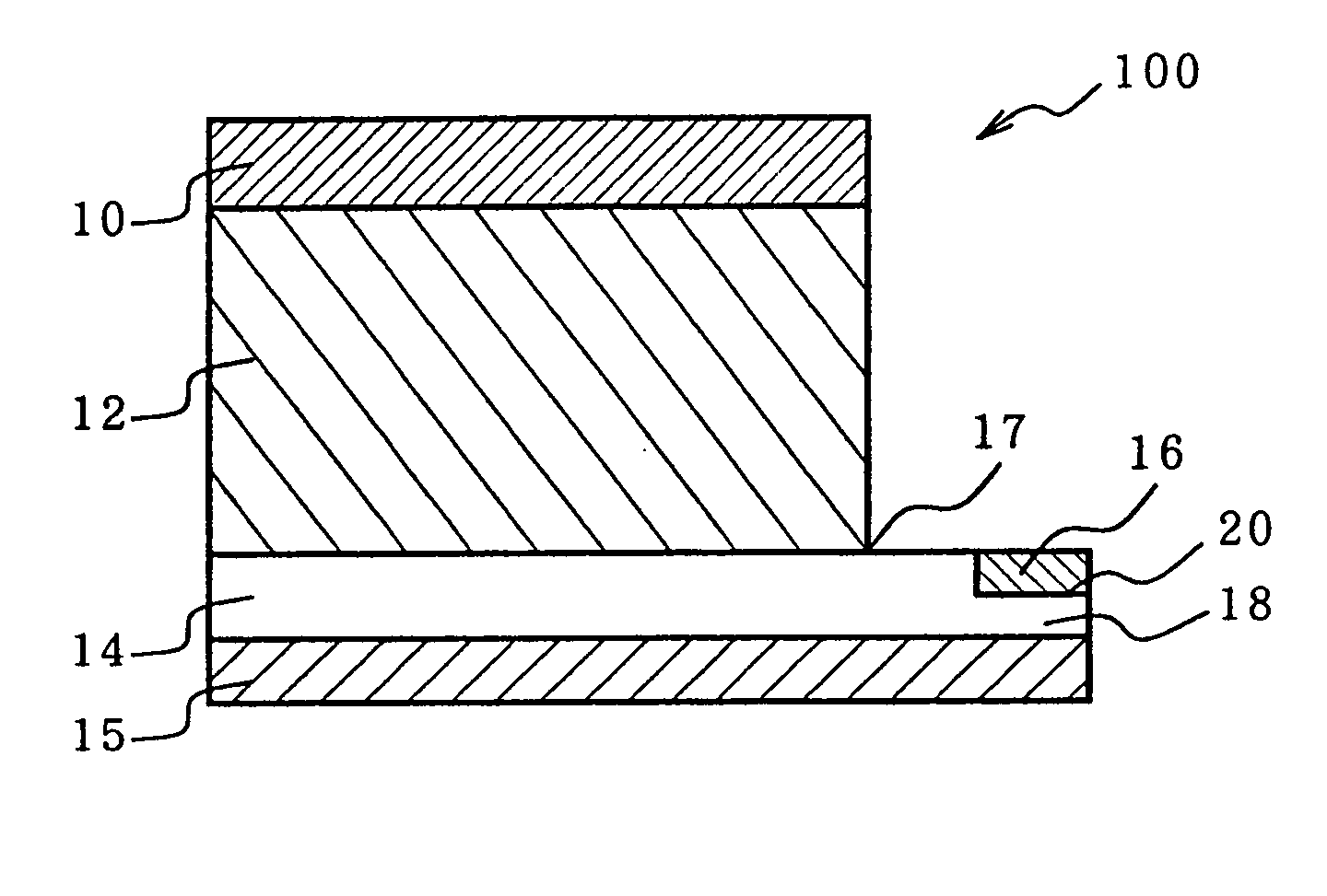
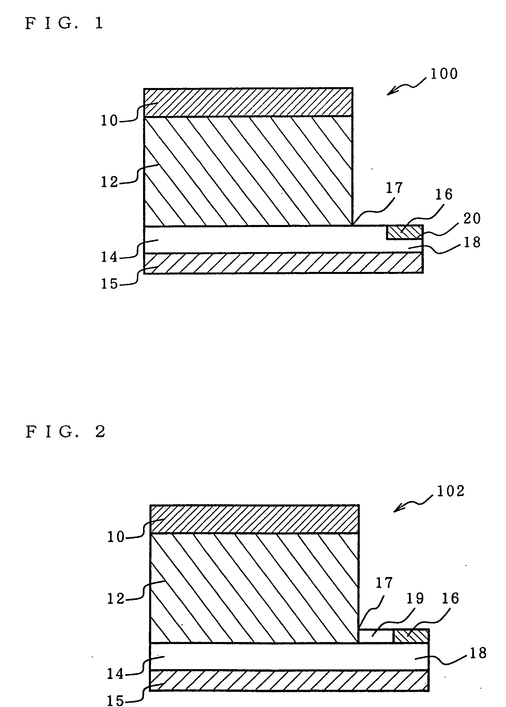
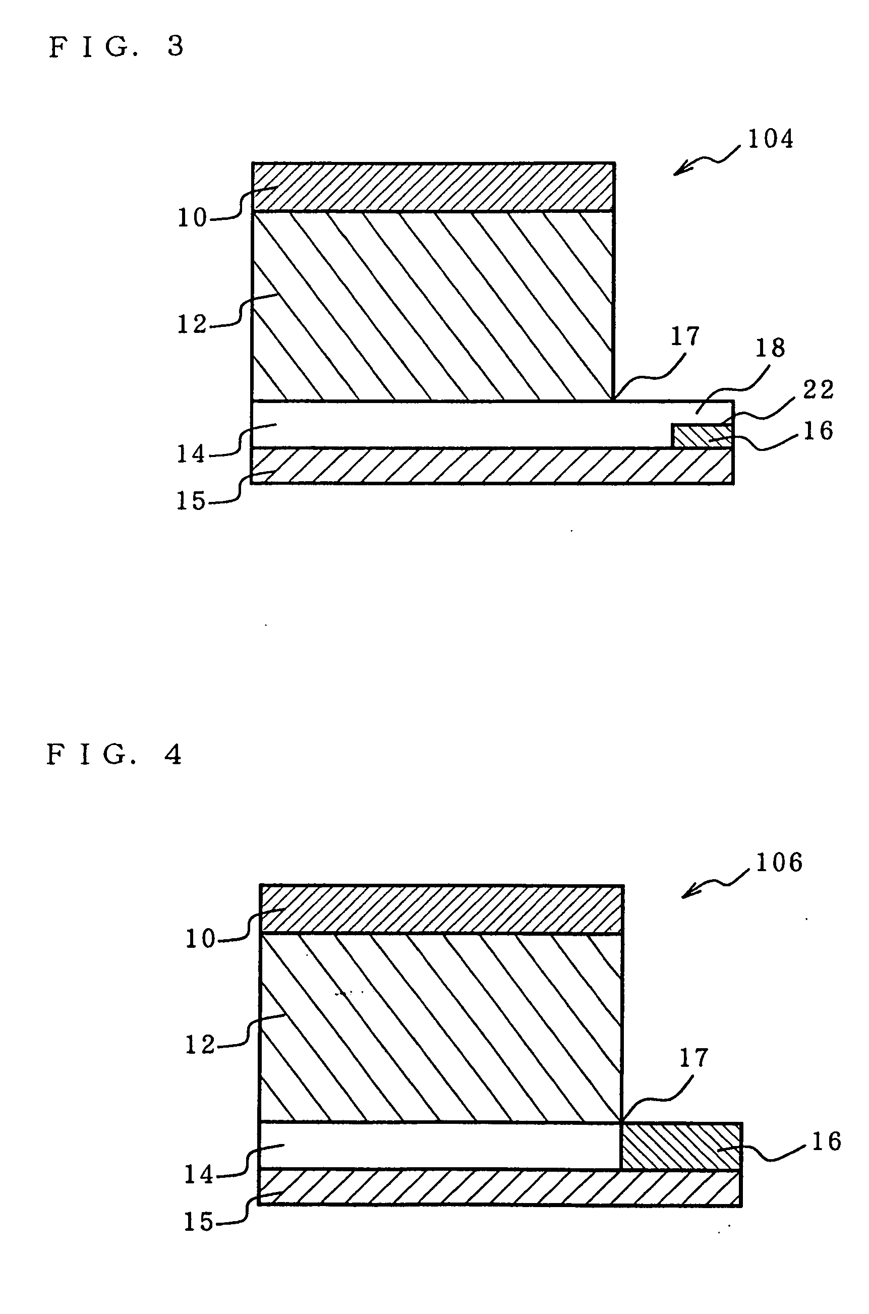
[0081] Referring now to FIG. 1, the first embodiment according to the present invention will be described. FIG. 1 is a cross-sectional view of an organic EL element in the first embodiment, wherein on the support substrate 15, a semiconductor layer 14 comprising non-monocrystal material, an organic light-emitting medium 12, and a cathode (first cathode) 10 are formed successively. To the extension 18 extended in the horizontal section from the edge section 17 of the semiconductor layer 14, the anode (second electrode) 16 is electrically connected.

[0082] Consequently, as the light may be taken out from the semiconductor layer 14 to the outside by configuring in this way, the light energy (or light intensity) can be increased. In addition, since the anode (second electrode) 16 and the cathode (first electrode) are not practically opposite to each other, a wide variety of electrode materials may be used and the electrical connection to the outside is facilitated. In addition, since th...

second embodiment

[0178] Referring now to FIG. 12(a) to FIG. 12(d), the manufacturing method of an organic EL element which is the second embodiment according to the present invention will be described in detail.

[0179]FIG. 12(a)-(d) is illustrations that schematically show the organic EL element in each process (step) of the manufacturing method related to the second embodiment. In the following discussion, the manufacturing method of the organic EL element is focused, and with respect to the component materials, and the like, the contents described for the first embodiment may apply.

(i) Formation of Anode (Second Electrode)

[0180]FIG. 12(a) shows the condition in which the anode (second electrode) 16 is installed on the support substrate 15.

[0181] The method for forming this anode 16 is not particularly limited, but the anode may be able to be formed in the specified location by combining sputtering (deposition method) and photolithography. Specifically, on the support substrate 15, the anode la...

example 1

(1) Fabrication of Organic EL Element

(i) Formation of the Cathode (Second Electrode)

[0192] A transparent glass substrate having a dimension of 1.1 mm(thickness)×200 mm(length)×200 mm (width) was ultrasonically cleaned and after drying in the N2 (nitrogen gas) environment, the glass substrate was cleaned by the use of UV (ultraviolet ray) and ozone further for 10 minutes. Then, on the cleaned glass substrate, a thin film (100 nm thick) comprising Al / Si alloy (Si concentration: 1 at. %) was formed by the use of the sputtering apparatus (available from ULVAC JAPAN, Ltd.). This Al / Si alloy thin film was patterned in lattices (line width: 20 μm; lattice pitch: 320 μm) by the use of photolithography as shown in FIG. 11(a). The construction of the configuration in which the cathode (second electrode) was electrically connected at the edge section of the semiconductor layer was intended.

(ii) Formation of the Semiconductor Layer

[0193] The glass substrate on which the cathode was forme...


PUM


Abstract

The present invention relates to an organic electroluminescence element and the manufacturing method thereof comprising an anode, semiconductor layer, organic light-emitting medium, and a cathode, an organic light-emitting medium is located between the first electrode and the semiconductor layer comprising the non-monocrystal material and the second electrode is electrically connected to the edge section of the semiconductor layer when either one of the anode or cathode is designated to the first electrode and the other electrode to the second electrode. Because the first electrode and the second electrode are configured in such a manner not to be opposite to each other in this way, various electrode materials are able to be used and the light-emitting area is able to be increased, and therefore, the organic EL element with the luminous energy taken out to the outside and a manufacturing method that can efficiently obtain such organic EL element are able to be provided.

Description

CROSS REFERENCE TO RELATED APPLICATION [0001] This is a continuation application of PCT International Application of PCT / JP00 / 02796 filed on Apr. 27, 2000.BACKGROUND OF THE INVENTION [0002] 1. Field of Invention [0003] The present invention relates to an organic electroluminescence element (hereinafter sometimes called the “organic EL element” or “EL element”) and the manufacturing method thereof. [0004] Particularly, the present invention relates to an organic EL element which has a large light-emitting area suited for noncommercial and industrial-use display devices (liquid displays and the like) and which can be used for various electrode materials and to the manufacturing method that can obtain such organic EL elements efficiently. [0005] 2. Description of Related Art [0006] One example of the conventional organic EL element is disclosed in, for example, JP-A-3-262170. Referring now to FIG. 13, the configuration is explained. An organic layer 202 is interposed between a first el...

Claims


Application Information

Patent Timeline
Patent Type & Authority Applications(United States)
IPC IPC(8): H01L27/32H01L51/52
CPCH01L27/32H01L51/5203H01L2251/5361H01L51/5221H01L51/5206H10K50/81H10K50/814H10K50/822H10K50/824H05B33/26H10K50/805H10K59/00
Inventor HOSOKAWA, CHISHIOKAWAMURA, HISAYUKINAKAMURA, HIROAKI
Owner IDEMITSU KOSAN CO LTD
Learn More