Polarization plate with optical compensation layer and image display device

a technology of optical compensation layer and polarizing plate, which is applied in the direction of polarizing elements, non-linear optics, instruments, etc., can solve the problems of affecting the reattachment of the polarizing plate with the optical compensation layer, and breaking the optical compensation layer and the liquid crystal display panel, etc., to achieve the effect of sufficient adhesiveness and easy reattachmen

Inactive Publication Date: 2005-06-02
NITTO DENKO CORP
View PDF4 Cites 47 Cited by
  • Summary
  • Abstract
  • Description
  • Claims
  • Application Information

AI Technical Summary

Benefits of technology

[0005] It is an object of the present invention to provide a polarizing plate with an optical compensation layer that has a sufficient adhesiveness when it is used in various image display apparatuses such as a liquid crystal display and can be peeled off without leaving a pressure-sensitive adhesive on the side of the image display apparatus and reattached easily.

Problems solved by technology

In such cases, it takes great effort to reattach the polarizing plate with the optical compensation layer.
Moreover, in the case where the pressure-sensitive adhesive and the surface of the glass substrate adhere to each other firmly, the power of peeling the polarizing plate with the optical compensation layer may break the optical compensation layer and a liquid crystal display panel, etc., for example.

Method used


Image

  • Polarization plate with optical compensation layer and image display device
  • Polarization plate with optical compensation layer and image display device
  • Polarization plate with optical compensation layer and image display device

Examples


example 1

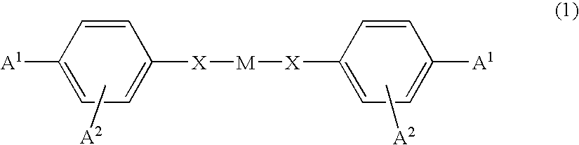
[0166] On a 50 μm thick triacetylcellulose (TAC) film (manufactured by Fuji Photo Film Co., Ltd.; trade name:T-50SH), 1 wt % PVA (manufactured by The Nippon Synthetic Chemical Industry Co., Ltd.; trade name:NH-18) aqueous solution was applied and dried at 90° C., thus forming a PVA coating having a thickness of equal to or smaller than about 0.01 μm. Then, a surface of this coating was rubbed so as to form an alignment film. On the other hand, a liquid crystal monomer represented by the formula (6) above (a polymerized rod-like nematic liquid crystal) and a chiral dopant represented by the formula (44) above were mixed such that the weight ratio between them were 7:3. This mixture was dissolved in toluene so as to obtain 40 wt % solution. Furthermore, a photopolymerization initiator (trade name: IRGACURE; manufactured by Ciba Specialty Chemicals) was added so as to account for 3 wt %, thereby preparing a coating solution. The coating solution was applied to the alignment film and su...

example 2

[0172] A polarizing plate with an optical compensation layer was obtained similarly to Example 1 above except for using as the pressure-sensitive adhesive (B) a pressure-sensitive adhesive solution (15 wt % toluene solution) prepared by adding 0.8 parts by weight of a cross-linking agent (polyfunctional isocyanate compound; manufactured by NIPPON POLYURETHANE INDUSTRY CO., LTD.) to 100 parts by weight (solids) of an acrylic polymer. The acrylic polymer had a weight ratio of butylacrylate / acrylic acid=100 / 3, a weight-average molecular weight of 1,500,000 and a glass transition temperature of −33° C.

examples 3 to 5 and reference example

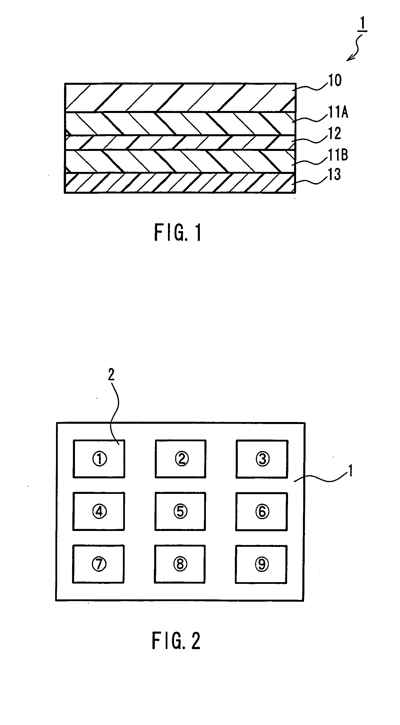
[0189] A polarizing plate with an optical compensation layer (300 mm×250 mm) in which the release film was formed on an exposed surface of the pressure-sensitive adhesive layer (B) was produced similarly to Example 1 above except that a commercially available polarizing plate (manufactured by Nitto Denko Corporation; trade name:SEG5224DU) was subjected to a heat treatment at a predetermined temperature for a predetermined period. The heating condition is shown in Table 2 below. Then, the release film was peeled off from the polarizing plate with the optical compensation layer. Via the exposed pressure-sensitive adhesive layer (B), the polarizing plate with the optical compensation layer was attached by roller onto a glass substrate (400 mm×400 mm). Thereafter, an untreated polarizing plate (manufactured by Nitto Denko Corporation; trade name:SEG5224DU) was further attached to the backside of the glass substrate in a crossed Nichols state using a pressure-sensitive adhesive. Using th...


PUM

PropertyMeasurementUnit
adhesive strengthaaaaaaaaaa
glass transition temperatureaaaaaaaaaa

Abstract

A polarizing plate with an optical compensation layer is provided, which has an excellent peelability and is easy to reattach after mounted on an image display apparatus. A pressure-sensitive adhesive layer satisfying the condition (I) below is formed on both surfaces of an optical compensation layer, and one of the pressure-sensitive adhesive layers is further laminated with a polarizing plate. condition (I): in the case where a pressure-sensitive adhesive layer causing the optical compensation layer and the polarizing plate to adhere to each other is expressed by a pressure-sensitive adhesive layer (A) and the other pressure-sensitive adhesive layer is expressed by a pressure-sensitive adhesive layer (B) and attached to a glass substrate, the pressure-sensitive adhesive layer (A) causing the optical compensation layer and the polarizing plate to adhere to each other has an adhesive strength exceeding 12 N / 25 mm, and the pressure-sensitive adhesive layer (B) causing the optical compensation layer and the glass substrate to adhere to each other has an adhesive strength of 1 to 10 N / 25 mm.

Description

TECHNICAL FIELD [0001] The present invention relates to a polarizing plate with an optical compensation layer and various image display apparatuses. BACKGROUND ART [0002] In a liquid crystal display, both surfaces of a liquid crystal cell in which a liquid crystal is retained are generally provided with a polarizing plate. In order to visually compensate for retardation caused by birefringence of the liquid crystal cell in a front direction and an oblique direction, a birefringent layer as an optical compensation layer is disposed between the liquid crystal cell and each of the polarizing plates. In practice, the optical compensation layer and the polarizing plate usually are formed as one piece serving as a polarizing plate with an optical compensation layer (see JP 5(1993)-27118 A and JP 5(1993)-27119 A, for example). [0003] Such a polarizing plate with an optical compensation layer generally has a configuration in which a first pressure-sensitive adhesive layer is formed on one s...

Claims


Application Information

Patent Timeline
Patent Type & Authority Applications(United States)
IPC IPC(8): C09K19/38G02F1/1335G02B5/30G02F1/13363H01L51/50H05B33/02H05B33/14
CPCG02B5/3033G02F1/13363G02F1/133528G02B5/3083G02F1/1335
Inventor YAMAOKA, TAKASHIADACHI, JUNICHIKAWAI, MASAYUKIMURAKAMI, NAOYOSHIMI, HIROYUKIYANO, SHUUJIWASAI, KANAKO
Owner NITTO DENKO CORP
Why Eureka
Try Eureka