Solid electrolytic capacitor

a solid electrolytic capacitor and capacitor technology, applied in the direction of electrolytic capacitors, capacitor electrodes, liquid electrolytic capacitors, etc., can solve the problems of unfavorable large size and weight of conventional solid electrolytic capacitors

Inactive Publication Date: 2005-06-02
ROHM CO LTD
View PDF3 Cites 24 Cited by
  • Summary
  • Abstract
  • Description
  • Claims
  • Application Information

AI Technical Summary

Benefits of technology

[0020] With such an arrangement, all the cathode layers can be easily fixed to the cathode lead by using the electroconductive paste. As noted above, the connection between all the cathode layers and the cathode lead results in reduction of the equivalent series resistance (ESR).

Problems solved by technology

Under these circumstances, the conventional solid electrolytic capacitor tends to be unfavorably large in size and weight in order to improve the capacitor performance in a high frequency range.

Method used


Image

  • Solid electrolytic capacitor
  • Solid electrolytic capacitor
  • Solid electrolytic capacitor

Examples


first embodiment

[0027] Reference is first made to FIGS. 1-3 illustrating a solid electrolytic capacitor 1 according to the present invention.

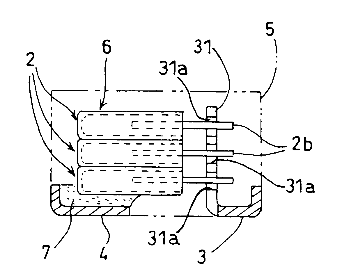
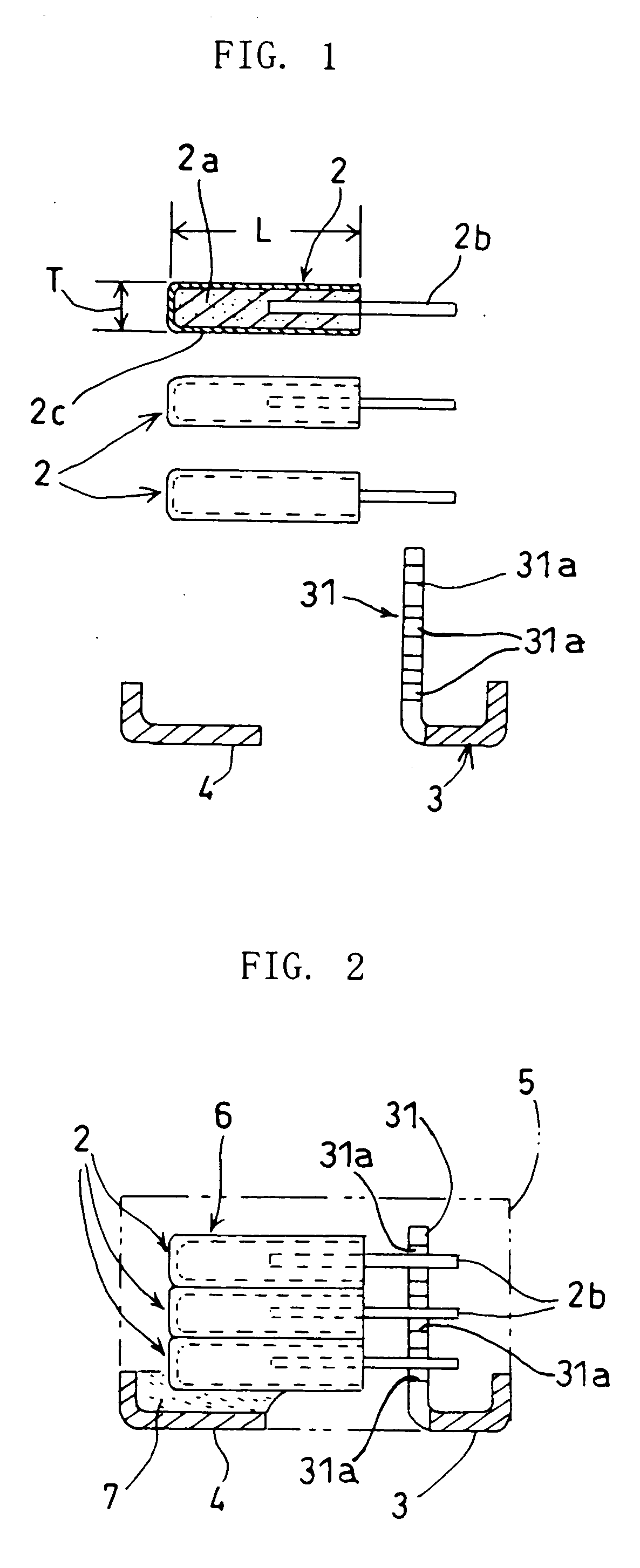
[0028] The solid electrolytic capacitor 1 includes a plurality of capacitor elements 2 (three elements shown in the figures), a pair of metal leads (right and left) 3 and 4, and a synthetic resin package 5 to entirely enclose the respective capacitor elements 2.

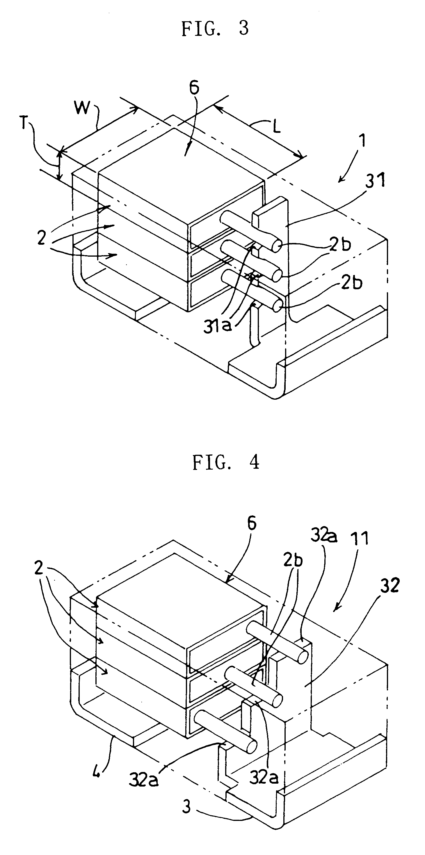
[0029] Each of the capacitor elements 2 includes a sintered chip 2a made of powdered valve metal and an anode wire 2b projecting from an end surface (“anode end surface”) of the chip 2a. The chip 2a is produced by compacting valve metal powder into a flat rectangular solid and then sintering this solid. The resultant chip 2a has prescribed thickness T, length L and width W (see FIG. 3), where the thickness T is smaller than the length L and the width W. Though not shown in the figures, the metal particles forming the chip 2a are covered by a dielectric layer, and upon this dielectric layer are formed a...

third embodiment

[0043]FIG. 5 shows a solid electrolytic capacitor 21 according to the present invention.

[0044] In this embodiment, for providing a capacitor element assembly 6, three adjacent capacitor elements 2 are arranged laterally (side by side) so that the stacking direction of the capacitor elements 2 is parallel to an upper supporting surface of the cathode lead 4. As seen from FIG. 5, the anode wires 2b of the respective capacitor elements 2 are at the same height and spaced laterally from each other. The anode wires 2b are welded to the flat upper end surface of an upright portion 33 of the anode lead 3. In the third embodiment, all the cathode layers 2c of the capacitor elements 2 are directly connected to the cathode lead 4 via electroconductive paste (not shown). The other features of the capacitor 21 are similar to those of the capacitor 1 of the first embodiment.

[0045] According to the third embodiment, all the cathode layers 2c of the capacitor element assembly 6 are held in direct...


PUM

PropertyMeasurementUnit
thicknessaaaaaaaaaa
lengthaaaaaaaaaa
widthaaaaaaaaaa

Abstract

A solid electrolytic capacitor includes a capacitor element assembly, an anode lead and a cathode lead. The assembly includes a plurality of capacitor elements each consisting of a sintered valve metal chip, an anode wire projecting from the chip, a solid electrolytic layer formed on the chip, and a cathode layer formed on the electrolytic layer. The chip of each capacitor element is flat, having a thickness smaller than its length and width. The capacitor elements are stacked in a thickness direction of the chip so that the cathode layers of the respective capacitor elements are connected to each other. The anode wires are fixed to the anode lead. At least one of the cathode layers is directly connected to the cathode lead.

Description

BACKGROUND OF THE INVENTION [0001] 1. Field of the Invention [0002] The present invention relates to a solid electrolytic capacitor utilizing the so-called valve metal such as tantalum or niobium. In particular, the present invention relates to a solid electrolytic capacitor provided with a pair of leads to enable mounting onto a printed circuit board, for example. [0003] 2. Description of the Related Art [0004] Typically, a solid electrolytic capacitor of the above-mentioned type comprises a capacitor element which includes a sintered porous chip and an anode wire projecting from an end surface of the chip. Such a porous chip is made of powdered valve metal such as tantalum or niobium, which is compacted into a rectangular solid or a circular column. The particles of the metal powder are covered by a highly insulating dielectric layer. The outer surface of the chip is formed with a solid electrolytic layer upon which a cathode layer is formed. The above-mentioned anode wire is conn...

Claims


Application Information

Patent Timeline
Patent Type & Authority Applications(United States)
IPC IPC(8): H01G9/26H01G2/06H01G9/00H01G9/012H01G9/032H01G9/04H01G9/048H01G9/052H01G9/10H01G9/15
CPCH01G2/06H01G9/012Y10T29/417H01G9/26H01G9/10
Inventor AUDO, HIDEKI
Owner ROHM CO LTD
Why Eureka
Try Eureka